|
A state has a
name and a description is associated
with a color - this will illustrate the inspection result in the Inspection
result panel. The criteria used to define the state are then given. The
combination of these criteria defines a state. These are general properties
in addition to state constraints. Commands to give an action if a state
occurs can additionally be given.
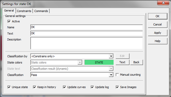
Below you see an
example of defining the general properties of a state.

- OK - closes the dialog
- Cancel - closes the dialog and cancels changes
- Apply - applies changes without closing
the dialog
- Help - activates the State Help pages
Classification
- Classification - Constraints only | Classification Tool
- Typical classification tools are ColorMatcher or TextureMatcher
- Edit will activate configuration dialog of Classification Tool
- State result - dynamic | static | state plus dynamic
- dynamic - equal to classification tool result
- static - equal to name of state
- state plus dynamic - dynamic prefixed with name of state
- State colors - can be static or reflect setup in classification
tools
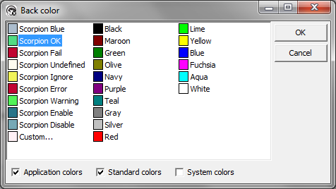
State Colors The
state colors are changed by double-clicking the Text and Back buttons for
text and background colors respectively. The color
is change using the Color Selector. Select a color and press OK.

Options
If the state is
not unique, an inspected unit can be accepted by more than one state. The
state highest in the state list is shown in the Inspection result
panel. The list can be sorted using the Up and Down buttons.
All commands related to the true states will however be run.
You can choose if
logs and curves are to be updated when a state is accepted. In our example
the state ‘Distance OK’ will update the logs and curves since measured
values are relevant when the state occurs. The ‘Can not measure’ and
‘No syringe’ states will however not update the logs and curves with any
values.
Note: Keep in history option very valuable
to avoid filling history list with images of no interest |