| Operating the Calibrator3D tool is in most cases quite
easy. Problems may arise when the linefinders fail to locate corners - this can
in most cases be fixed by tweaking the Traceline parameters. This guide
assumes you have generated a new Calibrator3D tool and opened its configuration
dialog.
Step 1
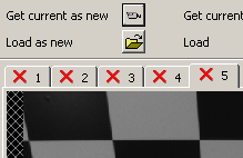
- Take snapshots (at least two, but about five is recommended) of the
scene with the calibrator object, and for each snapshot, click Get
current as new to import the picture into the Calibrator3D tool:
Step 2
- For each image, press Ctrl and left-click four corner points defining a
rectangle surrounding a number of squares.
- Note: The first clicked point MUST be the upper-left
corner of the rectangle. The order of the other points does not matter.
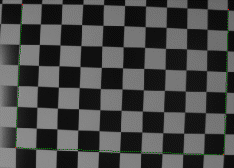
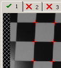
- Click Pick points. You should see most of the corners being
marked by a red '+', and the tab indicating OK
by a green tick.
Step 3
- When all images indicate OK, select an image to be the reference (click
Image is reference). The object origin will be indicated by a small
circle in the image.
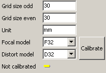
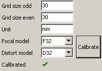
- Edit the dimensions and model parameters, then press Calibrate
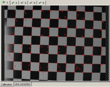
- You are done! The images will display the residuals as red arrows - they
are ideally "white noise" and should point in all directions.
- Click OK or Apply to save your changes.
Troubleshooting
Failed counting squares/Exception counting squares
- Adjust the line finder settings under Tracelines/Counting rectangles.
For each adjustment, go back to the Setup page and press Compute to
reevaluate the current image (you do not need to press Apply here).
- To investigate the problems, check Show counting details and press
Compute. This shows the edge points and lines found.
- To visualise your trace combs, also check Show tracelines and press
Compute.
Failed finding enough corners
- Adjust the line finder settings under Tracelines/Finding corners. For
each adjustment, go back to the Setup page and press Compute to reevaluate
the current image (you do not need to press Apply here).
- To investigate the problems, check Show corner details and press
Compute. This shows the edge points and lines found.
- To visualise your trace combs, also check Show tracelines and press
Compute.
- To recompute all images at once, press Compute all.
Residuals show a trend (not white noise), or the lens correction display shows
an irregular pattern
- The focal model or distort model may have been chosen too simple. In the
dropdown lists the top elements are the most complex, and are default
choices. The elements further down the lists are simpler models that give a
slight speed improvement at runtime.
- The calibration images do not cover enough of the image. It is
important to try to cover as much as possible of the screen when selecting
rectangles. It is possibly better to spread smaller rectangles around the
screen in several images.
|