|
This tool
measure
the difference between a located object and its model. The distance in space
between object and model is represented as a 2D image, where distance is
mapped to intensity. This tool needs an ordered point cloud.
Tool is currently incomplete.
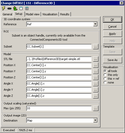
Setup
3D
coordinate system
- Reference - select a 3D reference
ROI
- Subset - currently, only a point cloud subset as delivered
from a ConnectedComponents tool can be used.
Model
- STL file - the CAD model file. Currently, only ASCII STL
(stereo lithography) files are supported.
- Position X,Y,Z - move the model
- Angle X,Y,Z - rotate the model
Output scaling (saturated)
- Max (pix 255) - in the output image, intensity represents the
spatial distance. Distances between 0 and Max will result in
intensity levels 0 to 255; any values above Max yields 255.
Output image (2D)
- Destination - pick a 2D image in Scorpion to receive the
distance mapping.

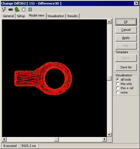
Model view
This view displays the CAD model as connected triangles (in red) and
plane normals (in yellow). You can customise the view, but this has no
significance for the tool's operation.

Constraints
(none yet defined)
Visualisation
|
Model |
CAD model, translated/rotated |
|
Normals |
Plane normals for CAD model |
Results
ExecuteCmd support (see also executeCmd)
|
Command
|
Parameters
|
Return values
|
Comments
|
|
|
|
|
|
|