|
The Calibrator tool handles lens distortion, lens magnification and
camera magnification using an Nth order nonlinear calibration based on a
precision grid.
The Calibrator tool is very important in 2D and 3D gauging applications.
Application areas:
-
High Precision Gauging
- 3D Machine Vision
- 2D and 3D Robot Vision
Demo Profile
Please note the following:
- In high precision gauging use the highest polynomial order possible
- increasing the polynomial order from 5 to 6 or even 7 have significant
effect on the precision. With Calibrator Scorpion support sub-pixel
measurement with precisions from 1/10th of pixel to 1/40th of a pixel.
Orders from 3 to 7 is supported by Scorpion. Order 7 may fail due to
lacking number of grid points - reduce order to 5 or 6 if this happens.
- In robot vision use 4 or 5 polynomial order. The primary purpose
for Calibrator in Robot Vision is to remove the lens distortion. Using
Calibrator Scorpion users can go closer and have pixel precision even
using wide-angle lenses of 4.8 mm or 6 mm
- Increasing the number of dots in the calibration grid will normally
increase the precision - decreasing the number of dots will make it a
little bit easier to get Calibrator to locate the dots.
- Outside the dot area the polynomial position estimate are unstable
- this effect will increase with the polynomial order.
- The Calibrator tool starts a reference chain and is the mother of
all reference systems in Scorpion.
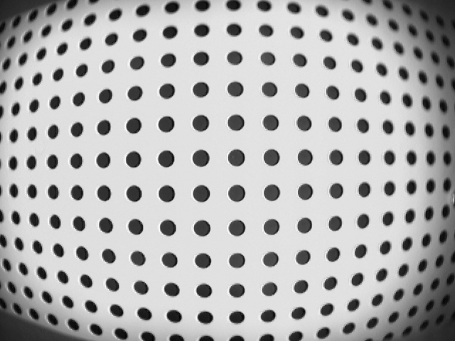
The image below is captured with 4.8 mm wide-angle lens. The grid has the
following properties:
- 15 rows and 22 columns
- Dot spacing of 50 mm
- Pixel resolution is 1,01 mm
The following corrections are performed with lens calibration:
-
The RMS position deviation is 0,3 mm or pixels
-
The maximum deviation is 0,8 mm
-
The edge points are moved 58,7 mm
The effect
of using the calibrator is that the optical precision is 0,3 mm.
Before correction the maximum error 2 * 58 mm = 116 mm. The maximum
error is thus reduced with a factor close to 300.
Using the ImageResampler
tool the following
perfect image can be created:
See also the Calibrated
Measurement example.
Test profiles on the Scorpion CD and online - click the links - are:
-
Calibrator - demonstration of sub-pixel measurement using
calibration
-
Calibrator - WideAngle Lens - demonstration of resampling and wide
angle lens calibration
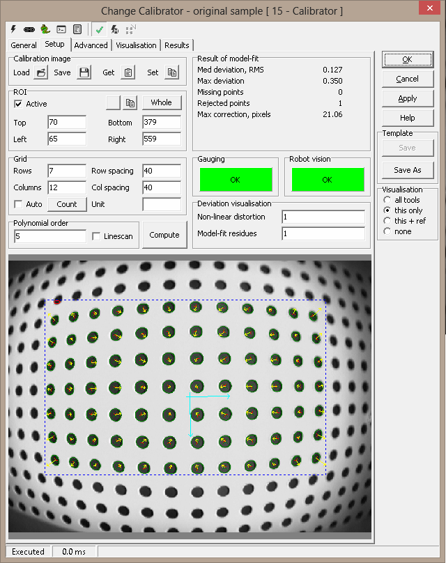
Setup
Calibration image
-
Load
 activates a file
browser activates a file
browser
- Save (...) saves the current image to file
-
Get current
 captures the current image and
creates a unique name captures the current image and
creates a unique name
ROI
Grid
- Rows/Columns - specifies the number of elements in the grid
- Row/Col spacing - physical distance between grid elements
- Unit - specified to document the physical unit
- Auto - if checked, automatically count the number of grid
elements when computing
- Count - if Auto is unchecked, counting is not done
automatically. Press Count to run the counting algorithm manually
Polynomial order - Specifies the order of the Calibrator tool.
Normally 5th order calibration is used - to improve accuracy an order of
six or seven may be tried. However, too high an order can also model
imperfections in the grid itself. In addition, the computation may fail with
a "Computational error" message.
Compute - Press this button to recompute the calibration file.
Deviation Visualisation - Yellow arrow displays the Non-linear
distortion - describes how the lens looks. The red arrows show the
Model-fit residues - these arrows shall be random - white noise. The radio
button sets the visualisation gain.
Gauging - indicates in green, yellow or red, the result of the
calibration for gauging applications (great need for accuracy)
Robot vision - indicates in green, yellow or red, the result of
the calibration for robot vision applications (less accuracy needed)
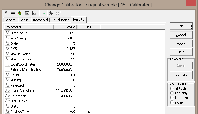
Result of model-fit
- Med deviation, RMS - specifies the average model fit given in
pixels - normally 0.1 - 0.5 pixels
- Max deviation - the maximum error in pixels
- Missing points - number of grid points missing
- Rejected points - number of points not accepted
- Max correction, pixels - displays the largest correction - with
wide angle lenses this can be as high as 25 pixels
Error messages
The calibrator may sometimes fail locating the grid points. If only a few
grid points are missing, the calibrator will ignore the corresponding grid
positions and still succeed. Likewise, extra grid points are in many cases
also rejected. In some cases the algorithm will fail, and no calibration
will be performed. Note that the grid points in the image must be regular
enough to form natural rows and columns. Only a limited amount of
perspective, skew or rotation can be corrected.
- Too few points found - not enough blobs found
- Too many points found - too many blobs found
- Too few points match - too few found blobs fit the grid points
- Bad grid - bad specification (rows, columns)
- Cannot find row - row cannot be built from blobs. (Too much
perspective or rotation?)
- Found row too short - not enough points found to form a row
- Too many points in row - too many points found that could
belong to a row
- Cannot estimate left blob position - could not deduce position
of leftmost grid point in row
- Cannot estimate mid blob position - could not deduce position
of middle point(s) in row
- Points too close in row - blobs too close to separate. (Maybe a
blob found inside another blob?)
- Computational error. Wrong polynomial order? - reduce the
polynomial order and try again
You can often rectify the situation by adjusting the blob search
parameters under the Advanced page. Turning off the Sobel filter can
often help with imperfect images.
Calibration Image Mouse Menu - activated by right clicking the image
- Add point to clipboard - Ctrl+LMouse - adds point to clipboard
- Reset Clipboard - Ctrl+Shift+RMouse - clears polygon on clipboard
- Copy objects - copies any overlay object into clipboard
- useful when configuring polygon tools
- Clipboard -
- Copy X - copies the x- cursor position to the clipboard
- Copy Y - copies the y-cursor position to the clipboard
- Copy point - copies x and y cursor position to the clipboard
- can be used to paste the position into a tool
- Remove last point - Ctrl-RMouse
- Remove first point
- Move point - Shift+Ctrl+RMouse - move selected point
- it can be easier to remove and insert a new point than
moving
- Insert point - Shift+LMouse
- Remove point - Shift+RMouse
- Smooth - smoothes the clipboard polygon
- Simplify - removes points on a straight line
- Undo - will undo last
operation
- Closed polygon - will open or close polygon
- Set measure origin - activates
image
measurements
- Measure - de/activates
image
measurements
- Freeze - freeze the
image
- Show info - displays a yellow label
image operation
- Copy image
without graphics
- Save shown image without graphics
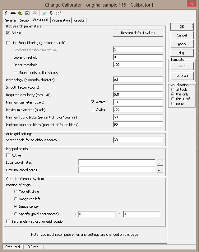
Advanced
Blob search parameters
- Active - activates the Advanced setup
- Restore default values - replace all values with defaults
- Use Sobel filtering (gradient search) - default on
- Gradient threshold (minimum) - The threshold can be lowered in low
contrast images if points are missing
- Lower threshold - lower blob threshold when sobel filtering is off
- Upper threshold - upper blob threshold when sobel filtering is off
- Search outside thresholds - invert meaning of thresholds
- Morphology (e=erode, d=dilate) - ed can improve point location when sobel
filtering is off
- Hint: Morphology should be off when Sobel filtering is active
- Smooth factor - Specifies the level of smoothing of the grid
points' blob contours
- Required circularity (max 1.0) - The value can be lowered if points are
missing
- Minimum diameter (pixels) - Minimum diameter to accept a grid point
- Maximum diameter (pixels) - Maximum diameter to accept a grid point
- Minimum found blobs (percent of rows*columns) - Percent of grid points found to accept calibration
image
- Minimum matched blobs (percent of found blobs) - Percent of found blobs accepted
as grid points
Auto grid settings
- Sector angle for neighbour search - where to search for
neighbour blobs when counting rows/columns. Turn off Auto and click
Count to visualise the effect of this setting
Output reference system
These settings adjust the placement of the calculated reference system.
The origin can be placed anywhere in the picture, regardless of the circle
positions in the calibration image. The angle can also be adjusted.
- Position of origin:
- Top left circle - default: the reference system origin is
centered at the upper left circle in the calibration image
- Image top left - origin is at the upper left corner of
the image (see note below)
- Image center - origin in the center of the image
- Specify (pixel coordinates) - origin anywhere in the
image (specified position)
- Zero angle - adjust for grid rotation - the angle of the
reference system is adjusted so that on average, the x axis is pointing
straight downwards in the picture. Note that with perspective in the
calibration image this may not work very well.
Note: Placing the origin outside the calibration circles may
introduce inaccuracies.
Hint: Using a fixed (pixel based) origin and a zero angle setting
will in general cancel the effects of the direction and position of the
calibration image. This will in general make recalibration easier.
Visualisation
|
Axes |
The
axes of the new reference system with calibrated coordinates.
|
Results
|
Pixel
size.x
|
The
average size of a pixel in x-direction (downwards)
|
|
Pixel size.y |
The average size of a pixel in y-direction
(to the right) |
ExecuteCmd support (see also executeCmd)
|
Command
|
Parameters
|
Return values
|
Comments
|
|
SaveImage |
Filename=<name> |
ok,None |
saves calibration image |
|
LoadImage |
Filename=<name> |
ok,None |
load calibration image. "Calculate" command has to be executed to
recalculate the new image. |
|
GetCurImage |
PREFILTER=<filter> |
ok,None |
replaces calibration image with current image. If Prefilter
parameter is included the value enables or disables prefilter |
|
Get |
Object=Image |
ok,handle |
returns HBITMAP of current calibration image |
|
Set |
Object=Image;
Destination=<imagename> |
ok,None |
set current calibration image to destination image (view) |
|
Count |
ROI=0/1
LEFT=n
TOP=n
RIGHT=n
BOTTOM=n |
ok,(nx,ny) |
count dots in current image. Note that all parameters are optional,
if not given the origin values will be used. |
|
Compute |
ROI=0/1
LEFT=n
TOP=n
RIGHT=n
BOTTOM=n
AUT0=0/1
ROWS=n
COLS=n
ROWSPACING=n
COLSPACING=n
POLORDER=n |
ok,((x,y),rms) |
computes calibration. Note that all parameters are optional,
if not given the origin values will be used. |
Example 1, recalibrate due to small or large calibration image
def Recalibrate():
  cal=GetTool('calib')
  print cal.executeCmd('GetCurImage')
  if GetBoolValue('Setup.Small'):
     print cal.executeCmd('Compute','POLORDER=5;ROWS=17;COLS=22;ROWSPACING=10;COLSPACING=10')
  else:
     print cal.executeCmd('Compute','POLORDER=6;ROWS=22;COLS=30;ROWSPACING=10;COLSPACING=10')
|
