|
Tool Name:
| ExternalData |
|
Tool Index: |
66 |
|
Tool Category: |
Data Tools |
| |
|
Description:
The ExternalData tool is a data tool which holds state information for one
or more states. The state can be of any of the following data types -
(a) Scalar - floating point value
(b) Text - string value
(c) Logic - boolean value
(d) Circle - 2D circle, as x and y coordinates of the center of the circle
and radius of the circle
(e) Point - 2D point, as x and y coordinates
(f) Line - 2D line, as x and y coordinates of the stat point and x and y
coordinates of the end point of the line
(g) Point 3D - 3D point, as x, y and z coordinates
(h) Line 3D - 2D line, as x, y and z coordinates of the stat point and x, y
and z coordinates of the end point of the line
(i) Sphere 3D - 3D sphere, as x, y and z coordinates of the center of the
sphere and radius of the sphere
Since ExternalData is able to manage multiple states simultaneously, it can
be used to collectively manage multiple data types, instead of configuring a
separate data tool for every state.
Like other tools from the 'Data Tools' tool category,
the ExternalData tool does not do any processing. It is used for holding
one or more states. The ExternalData tool can be accessed from other tools
defined in the profile, and the scripts configured in the Scorpion, for
getting or setting value of any of the configured data types.
All the tools from the 'Data Tools' category are used
primarily for -
-
Holding one or more states. This is
very similar to variables used in Python script which are
used for holding states. Data tools however have more
settings, inline with the Scorpion architecture, for more
control on the states they hold. Other tools and the scripts
defined in the profile can query current value and can also
set the value for any state held by a data tool.
-
Interfacing with user interface
elements. The Scorpion Vision Software support very useful
feature of customized user interface, for controlling the
processing at run-time, by setting values for different
processing parameters. Though it is possible to directly
link the user interface elements to the processing tools, it
is a recommended practice to use data tools as intermediate
layer to interface with the user interface elements and
actual processing tools linking to the data tools. This
provides better separation of user interface and processing,
and hence helps in reducing the setup, fine-tuning and
maintenance time.
User Interface:
(A) Tool Configuration dialog box – Setup Tab, Reference Sub-tab
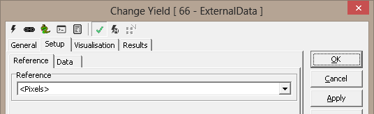
1. The ‘Reference’ drop down can be used to select the
input 2D reference or the input 3D reference. The input 2D reference provides the origin (0,0) and
rotation of the X and Y-axis. The input 3D reference provides the origin
(0,0,0) and rotation of the X, Y and Z axes. It is strongly recommended to click on the
'Apply' button available on the main tool configuration window, to apply the
newly selected input reference. This reference is then used while
configuring all other tool parameters.
(B) Tool Configuration dialog box – Setup Tab, Data Sub-tab
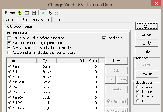
1. The ‘External data’ group can be used for defining data
types managed by the ExternalData tool.
2. The ‘Set to initial value before inspection’ check-box
can be used to reset the value of all the configured data types,
to their configured initial value, before every inspection cycle.
3. The ‘Make external changes permanent’ check-box can be
used to make the values persistent, which means that values of all the
configured data types are remembered across the session. The last values of
all the configured data types are remembered when the
profile is closed and the values of all the configured data types are set to these remembered
values when the profile is loaded next time.
4. The ‘Always transfer pasted values to results’ check-box can be
used to immediately transferring all the pasted values to results when the
'Paste ROI from Clipboard' button is clicked.
5. The 'Autotransfer initial value changes to result'
check-box can be used to enable the automatic transfer of the changed
initial values to the results, as soon as the initial values of changed and
saved by the user, from the user interface.
6. It has the list of the currently configured data type. Each row of the
list describes the name of the configured data type, its type and its
initial value. It is possible to select one or more data types from this
list. Clicking on the blank space in the data types list, rests the data
type selection and no data type is selected. A single data type can be
selected by clicking on it. For selecting multiple data type, CTRL keyboard
button can be kept pressed and the required tools can be clicked one by one.
Mouse right click anywhere in the list, pops up a menu. It has the
sub-menus, which have same functionality as all the buttons available on the
right hand side of the list box.
7. The 'New' button can be clicked to configure a new data
type. Data type configuration dialog box is popped up when the New button is
clicked.
Details about the settings available on this Data type configuration dialog
box, are described in the next sub-section on this page.
8. The 'Edit' button is enabled whenever a single data type
from the list of currently configured data types is selected. The Edit
button can be clicked to pop up the Data type configuration dialog box for
the current selected data tye.
Name and the initial value of the data type can be edited from the edit data
type dialog box. The type can not be edited, once a data type is added to
the ExternalData tool.
9. The 'Up' button is enabled whenever one or more data
types from the list of currently configured data types are selected. The Up
button can be clicked to change the sequence of the listed data types, by
moving the currently selected data types up by one position.
10. The 'Down' button is enabled whenever one or more data
types from the list of currently configured data types are selected. The
Down button can be clicked to change the sequence of the listed data types,
by moving the currently selected data types down by one position.
11. The 'Delete' button is enabled whenever one or more
data types from the list of currently configured data types are selected.
The Delete button can be clicked to delete the currently selected data
types. To avoid problems with accidental button click, a user confirmation
message box is popped up before actual deletion of the data type is
performed.
12. The 'Transfer selected initial values to results'
button is enabled whenever one or more data types from the list of currently
configured data types are selected. The Transfer selected initial values to
results button can be clicked to set the values of the results of the
ExternalData tool, to the corresponding configured initiial values, for the
selected data types.
13. The 'Transfer results to selected initial values'
button is enabled whenever one or more data types from the list of currently
configured data types are selected. The Transfer results to selected initial
values button can be clicked to set the initial values of the selected data
types to the corresponding result values.
14. The 'Transfer all initial values to results' button can
be clicked to set the values of the results of the ExternalData tool, to the
corresponding configured initial values, for all the configured data types.
15. The 'Transfer results to selected initial values'
button can be clicked to set the initial values of all the configured data
types to the corresponding result values.
16. The ‘Paste ROI from Clipboard’ button is enabled if any
single 2D data type from the list of currently configured data types is
selected. Point and Line are the 2D data types supported in the current
version. The 'Paste ROI from Clipboard' button can be used to
copy user defined selection from the clipboard to the initial values
of the selected data type.
If Point type data type is selected from the list of the configured data
types, it is expected that a single point is defined on the image by
pressing the CTRL keyboard key and simultaneously using mouse left button
click to define the target point. If no point is defined on the image or a
line or a polygon is defined on the image, clicking on the 'Paste ROI from
Clipboard' has no effect when a Point type data type is selected.
If Line type data type is selected from the list of the configured data
types, it is expected that a line point is defined on the image by pressing
the CTRL keyboard key and simultaneously using mouse left button click to
define the target points which indicate start point and end point of the
line. If less than 2 points are selected or a polygon is defined on the
image, clicking on the 'Paste ROI from Clipboard' has no effect when a Line
type data type is selected.
17. The ‘Copy ROI to Clipboard’ button is enabled if any
single 2D data type from the list of currently configured data types is
selected. Point and Line are the 2D data types supported in the current
version. Copy ROI to Clipboard button can be used
to copy the initial values of the selected data type, to the clipboard. This is useful in
viewing the exact location of the configured initial values on the inspection image and
fine-tuning, if required.
18. The 'Outgoing 2D reference based on' dropdown can be
used to specify the output reference from the ExternalData tool. It can
selected as 'Incoming reference' or as any of the configured 2D data types -
Point, Line or Cicle.
If the incoming reference is a 3D reference, for all 2D types configured,
the incoming 3D reference is converted to a 2D reference as a plane with
z=0, with respect to the incoming reference.
If the 'Incoming reference' option is selected as 'Outpoint 2D reference',
the outgoing 2D reference is same as the incoming reference. If incoming
reference is a 3D reference, the incoming 3D reference is converted to a 2D
reference as a plane with z=0, with respect to the incoming reference, and
then this 2D reference is the outgoing reference
If any of the Point type data types is selected as 'Outpoint 2D reference',
the origin of the outgoing reference is set to the current value of the
selected Point type data type. The orientation of the X and Y axes remains
the same as the incoming reference.
If any of the Line type data types is selected as 'Outpoint 2D reference',
the origin of the outgoing reference is set to the current value of the
starting point of the selected Line type data type. The orientation of the X
axis is set in the direction of the current values if the line - from
starting point to the end point. The orientation of the Y axis is set to 90
degrees with respected to the new X axis.
If any of the Circle type data types is selected as 'Outpoint 2D reference',
the origin of the outgoing reference is set to the current value of the
center point of the selected Circle type data type. The orientation of the X
and Y axes remains the same as the incoming reference.
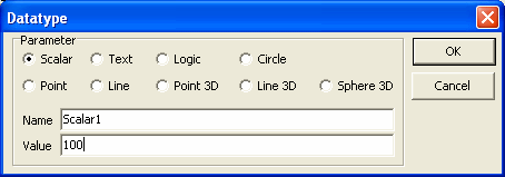
(C) New Data Type Configuration dialog box
1. When the 'New' button on the ExternalData tool configuration
dialog box is clicked, the new data type configuration dialog box is popped
up.
2. The type of the data type can be selected using the available radio
buttons. The type can be any one of the following - Scalar, Text, Logic,
Circle, Point, Line, Point 3D, Line 3D, Sphere 3D.
3. Name of the new data type can be specified in the text box next to the
'Name'. It should be a unique name within the current
ExternalData tool configuration, which means that duplicate names are not
allowed.
4. The initial value for the new data type can be typed in the text box next
to the 'Value'. The format for the 'Value' string is
different for different types.
For Scalar type data type, any floating point value can be typed as the
initial value.
5. For Text type data type, any string value can be typed as the initial
value.
6. For Logic type data type, 0 (false) or 1 (true) value can be typed as the
initial value.
7. For Circle type data type, initial value should be typed as a string in
the format (x;y)(r), where x is the x coordinate of the center of the
circle, y is the y coordinate of the center of the circle, r is the radius
of the circle. Please note that the string format should exactly match with
the expected format with brackets and semi-colon characters, as specified.
8. For Point type data type, initial value should be typed as a string in
the format (x;y), where x is the x coordinate of the point, y is the y
coordinate of the point. Please note that the string format should exactly
match with the expected format with brackets and semi-colon characters, as
specified.
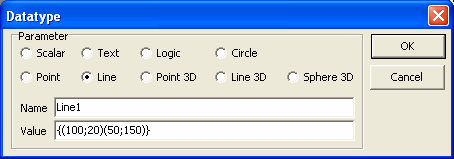
9. For Line type data type, initial value should be typed as a string in the
format {(x1;y1)(x2;y2)}, where x1 is the x coordinate of the start point of
the circle, y1 is the y coordinate of the start point of the line, x2 is the
x coordinate of the end point of the circle, y2 is the y coordinate of the
end point of the line. Please note that the string format should exactly
match with the expected format with brackets and semi-colon characters, as
specified.

10. For Point 3D type data type, initial value should be typed as a string
in the format (x;y;z), where x is the x coordinate of the point, y is the y
coordinate of the point, z is the z coordinate of the point. Please note
that the string format should exactly match with the expected format with
brackets and semi-colon characters, as specified.
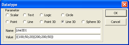
11. For Line 3D type data type, initial value should be typed as a string in
the format {(x1;y1,z1)(x2;y2,z2)}, where x1 is the x coordinate of the start
point of the circle, y1 is the y coordinate of the start point of the line,
z1 is the z coordinate of the start point of the line, x2 is the x
coordinate of the end point of the circle, y2 is the y coordinate of the end
point of the line, z2 is the z coordinate of the end point of the line.
Please note that the string format should exactly match with the expected
format with brackets and semi-colon characters, as specified.
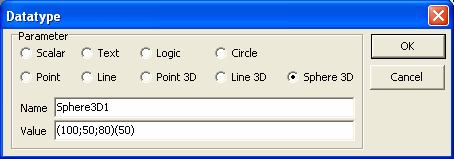
12. For Sphere 3D type data type, initial value should be typed as a string
in the format (x;y;z)(r), where x is the x coordinate of the center of the
sphere, y is the y coordinate of the center of the sphere, z is the z
coordinate of the center of the sphere, r is the radius of the sphere.
Please note that the string format should exactly match with the expected
format with brackets and semi-colon characters, as specified.
Basic Processing when the tool is executed:
1. If 'Set to initial value before inspection' is enabled,
the value of all the configured data types are reset to their respective initial
value.
|
Inputs to the Tool: |
| Inputs: |
None |
| Uses Reference: |
Yes, uses a 2D reference or a 3D
reference |
| Uses Image: |
No |
| |
|
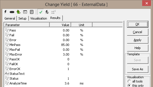
Results
|
Outputs from the Tool: |
| Outputs: |
|
1 |
[Scalar
DataType
Name]: |
Numeric |
The current value of
the
configured
scalar data
type. This
is a
floating
point value.
Name of the
output
variable
'[Scalar
DataType
Name]'
indicates
the name of
the
configured
scalar data
type. |
|
2 |
[Text
DataType
Name]: |
String |
The current value of
the
configured
text data
type. This
is a
string value.
Name of the
output
variable
'[Text
DataType
Name]'
indicates
the name of
the
configured
text data
type. |
|
3 |
[Logic
DataType
Name]: |
Boolean |
The current value of
the
configured
logic data
type. This
is a
boolean value,
0 (false) or
1 (true).
Name of the
output
variable
'[Logic
DataType
Name]'
indicates
the name of
the
configured
logic data
type. |
|
4 |
[Circle
DataType
Name]_x: |
Numeric |
The current value of
the x
coordinate
of the
center point
of the
configured
circle data
type. This
is a
floating
point value.
String
'[Circle
DataType
Name]' in
the name of
the output
variable
indicates
the name of
the
configured
circle data
type. |
|
5 |
[Circle
DataType
Name]_y: |
Numeric |
The current value of
the y
coordinate
of the
center point
of the
configured
circle data
type. This
is a
floating
point value.
String
'[Circle
DataType
Name]' in
the name of
the output
variable
indicates
the name of
the
configured
circle data
type. |
|
6 |
[Circle
DataType
Name]_r: |
Numeric |
The current value of
the radius
of the
configured
circle data
type. This
is a
floating
point value.
String
'[Circle
DataType
Name]' in
the name of
the output
variable
indicates
the name of
the
configured
circle data
type. |
|
7 |
[Point
DataType
Name]_x: |
Numeric |
The current value of
the x
coordinate
of the
configured
point data
type. This
is a
floating
point value.
String
'[Point
DataType
Name]' in
the name of
the output
variable
indicates
the name of
the
configured
point data
type. |
|
8 |
[Point
DataType
Name]_y: |
Numeric |
The current value of
the y
coordinate
of the
configured
point data
type. This
is a
floating
point value.
String
'[Point
DataType
Name]' in
the name of
the output
variable
indicates
the name of
the
configured
point data
type. |
|
9 |
[Line
DataType
Name]_p_x: |
Numeric |
The current value of
the x
coordinate
of the
starting
point of the
configured
line data
type. This
is a
floating
point value.
String
'[Line
DataType
Name]' in
the name of
the output
variable
indicates
the name of
the
configured
line data
type. |
|
10 |
[Line
DataType
Name]_p_y: |
Numeric |
The current value of
the y
coordinate
of the
starting
point of the
configured
line data
type. This
is a
floating
point value.
String
'[Line
DataType
Name]' in
the name of
the output
variable
indicates
the name of
the
configured
line data
type. |
|
11 |
[Line
DataType
Name]_v_x: |
Numeric |
The current value of
the x
component of
the Scorpion
line vector
of the
configured
line data
type. This
is a
floating
point value.
String
'[Line
DataType
Name]' in
the name of
the output
variable
indicates
the name of
the
configured
line data
type. |
|
12 |
[Line
DataType
Name]_v_y: |
Numeric |
The current value of
the y
component of
the Scorpion
line vector
of the
configured
line data
type. This
is a
floating
point value.
String
'[Line
DataType
Name]' in
the name of
the output
variable
indicates
the name of
the
configured
line data
type. |
|
13 |
[Point 3D
DataType
Name]_x: |
Numeric |
The current value of
the x
coordinate
of the
configured
point3D data
type. This
is a
floating
point value.
String
'[Point 3D
DataType
Name]' in
the name of
the output
variable
indicates
the name of
the
configured
point3D data
type. |
|
14 |
[Point 3D
DataType
Name]_y: |
Numeric |
The current value of
the y
coordinate
of the
configured
point3D data
type. This
is a
floating
point value.
String
'[Point 3D
DataType
Name]' in
the name of
the output
variable
indicates
the name of
the
configured
point3D data
type. |
|
15 |
[Point 3D
DataType
Name]_z: |
Numeric |
The current value of
the z
coordinate
of the
configured
point3D data
type. This
is a
floating
point value.
String
'[Point 3D
DataType
Name]' in
the name of
the output
variable
indicates
the name of
the
configured
point3D data
type. |
|
16 |
[Line 3D
DataType
Name]_p_x: |
Numeric |
The current value of
the x
coordinate
of the
starting
point of the
configured
line3D data
type. This
is a
floating
point value.
String
'[Line 3D
DataType
Name]' in
the name of
the output
variable
indicates
the name of
the
configured
line3D data
type. |
|
17 |
[Line 3D
DataType
Name]_p_y: |
Numeric |
The current value of
the y
coordinate
of the
starting
point of the
configured
line3D data
type. This
is a
floating
point value.
String
'[Line 3D
DataType
Name]' in
the name of
the output
variable
indicates
the name of
the
configured
line3D data
type. |
|
18 |
[Line 3D
DataType
Name]_p_z: |
Numeric |
The current value of
the z
coordinate
of the
starting
point of the
configured
line3D data
type. This
is a
floating
point value.
String
'[Line 3D
DataType
Name]' in
the name of
the output
variable
indicates
the name of
the
configured
line3D data
type. |
|
19 |
[Line 3D
DataType
Name]_v_x: |
Numeric |
The current value of
the x
component of
the Scorpion
3D line
vector of
the
configured
line3D data
type. This
is a
floating
point value.
String
'[Line3D
DataType
Name]' in
the name of
the output
variable
indicates
the name of
the
configured
line3D data
type. |
|
20 |
[Line 3D
DataType
Name]_v_y: |
Numeric |
The current value of
the y
component of
the Scorpion
3D line
vector of
the
configured
line3D data
type. This
is a
floating
point value.
String
'[Line 3D
DataType
Name]' in
the name of
the output
variable
indicates
the name of
the
configured
line3D data
type. |
|
21 |
[Line 3D
DataType
Name]_v_z: |
Numeric |
The current value of
the z
component of
the Scorpion
3D line
vector of
the
configured
line3D data
type. This
is a
floating
point value.
String
'[Line 3D
DataType
Name]' in
the name of
the output
variable
indicates
the name of
the
configured
line3D data
type. |
|
22 |
[Sphere 3D
DataType
Name]_x: |
Numeric |
The current value of
the x
coordinate
of the
center point
of the
configured
sphere3D
data type. This
is a
floating
point value.
String
'[Sphere 3D
DataType
Name]' in
the name of
the output
variable
indicates
the name of
the
configured
sphere3D
data type. |
|
23 |
[Sphere 3D
DataType
Name]_y: |
Numeric |
The current value of
the y
coordinate
of the
center point
of the
configured
sphere3D
data type. This
is a
floating
point value.
String
'[Sphere 3D
DataType
Name]' in
the name of
the output
variable
indicates
the name of
the
configured
sphere3D
data type. |
|
24 |
[Sphere 3D
DataType
Name]_z: |
Numeric |
The current value of
the z
coordinate
of the
center point
of the
configured
sphere3D
data type. This
is a
floating
point value.
String
'[Sphere 3D
DataType
Name]' in
the name of
the output
variable
indicates
the name of
the
configured
sphere3D
data type. |
|
25 |
[Sphere 3D
DataType
Name]_r: |
Numeric |
The current value of
the radius
of the
configured
sphere3D
data type. This
is a
floating
point value.
String
'[Sphere 3D
DataType
Name]' in
the name of
the output
variable
indicates
the name of
the
configured
sphere3D
data type. |
|
26 |
StatusText: |
Text |
This is a
standard
output from
all Scorpion
tools and
describes
the
processing
status |
|
27 |
Status: |
Numeric |
This is a
standard
output from
all Scorpion
tools and
indicates
error/success
of the tool
processing.
1 indicates
success and
0 indicates
error. |
|
28 |
AnalyzeTime: |
Numeric |
This is a
standard
output from
all Scorpion
tools and
indicates
the time
taken by the
last
processing
operation of
this tool |
Notes -
1. The outputs from a ExternalData tool are
not constants. They change depending on the
data types configured in the ExternalData
tool. Hence while deleting or editing name
of any of the data types, already configured
in the ExternalData tool, it is important to
check linking of those data types in the
other Scorpion tools and scripts, to avoid
possible breakages of links and to avoid
possibility of unexpected results due to the
same.
2. The configured data types are reflected
in the results tab, only when value of that
variable is transferred to results by
clicking on either 'Transfer selected
initial values to results' or 'Transfer all
initial values to results' buttons. It is
hence recommended to transfer values of any
new data type configured, to the results, as
soon as the new data type is added.
|
| Visualizations: |
|
1 |
[Circle
DataType
Name]: |
Displays
the circle as
per the
current
values, with
respect to
the incoming
reference.
If the
incoming
reference is
a 3D
reference;
the plane of
the incoming
3D
reference,
with z=0, is
used as an
internal 2D
reference
for drawing
the circle.
The string
'[Circle
DataType
Name]' in
the name of
the output
variable
indicates
the name of
the
configured
circle data
type. |
|
2 |
[Point
DataType
Name]: |
Displays
the point as
per the
current
values, with
respect to
the incoming
reference.
If the
incoming
reference is
a 3D
reference;
the plane of
the incoming
3D
reference,
with z=0, is
used as an
internal 2D
reference
for drawing
the point.
The string
'[Point
DataType
Name]' in
the name of
the output
variable
indicates
the name of
the
configured
point data
type. |
|
3 |
[Line
DataType
Name]: |
Displays
the line as
per the
current
values, with
respect to
the incoming
reference.
If the
incoming
reference is
a 3D
reference;
the plane of
the incoming
3D
reference,
with z=0, is
used as an
internal 2D
reference
for drawing
the line.
The string
'[Line
DataType
Name]' in
the name of
the output
variable
indicates
the name of
the
configured
line data
type. |
|
4 |
[Point 3D
DataType
Name]: |
Displays
the 3D point as
per the
current
values, with
respect to
the incoming
reference.
If the
incoming
reference is
a 2D
reference;
the 3D point
is not
displayed,
even if the
visualization
is enabled
for it. The
string
'[Point 3D
DataType
Name]' in
the name of
the output
variable
indicates
the name of
the
configured
point3D data
type. |
|
5 |
[Line 3D
DataType
Name]: |
Displays
the 3D line as
per the
current
values, with
respect to
the incoming
reference.
If the
incoming
reference is
a 2D
reference;
the 3D line
is not
displayed,
even if the
visualization
is enabled
for it. The
string
'[Line 3D
DataType
Name]' in
the name of
the output
variable
indicates
the name of
the
configured
line3D data
type. |
Notes -
1. The configured data types, for which
visualization is supported, are reflected in
the visualization tab, only when value of
that variable is transferred to results by
clicking on either 'Transfer selected
initial values to results' or 'Transfer all
initial values to results' buttons. It is
hence recommended to transfer values of any
new data type configured, to the results, as
soon as the new data type is added.
|
| Reference outputs: |
Yes, 2D reference as per configuration |
| |
|
|
Templates: |
| Supports Templates: |
No |
| |
|
