|
Tool Name:
| ExternalLine |
|
Tool Index: |
38 |
|
Tool Category: |
Data Tools |
| |
|
Description:
The ExternalLine tool is a data tool which holds state information, in form
of a line. The line can be defined in different modes -
(a) as a start point and an end point - x and y coordinates of the start
point, and x and y coordinates of the end point, where all values are
floating point values
(b) as a start point and a vector - x and y coordinates of the start point,
and x and y coordinates representing a vector, where all values are floating
point values
(c) as a start point and a length value and an angle value - x and y
coordinates of the start point, and length and angle of the line, where all
values are floating point values, and the angle is in degrees.
Like other tools from the 'Data Tools' tool category,
the ExternalLine tool does not do any processing. It is used for holding
state. The ExternalLine tool can be accessed from other tools defined in
the profile, and the scripts configured in the Scorpion, for getting or
setting a floating point value.
However, since the output values from the ExternalLine tool
include all values for all the 3 supported modes, as described above; it is
possible to use the ExternalLine tool as a mode converter, which can convert
representation of a line from any of the 3 supported modes to any of the other
supported modes.
All the tools from the 'Data Tools' category are used
primarily for -
-
Holding one or more states. This is
very similar to variables used in Python script which are
used for holding states. Data tools however have more
settings, inline with the Scorpion architecture, for more
control on the states they hold. Other tools and the scripts
defined in the profile can query current value and can also
set the value for any state held by a data tool.
-
Interfacing with user interface
elements. The Scorpion Vision Software support very useful
feature of customized user interface, for controlling the
processing at run-time, by setting values for different
processing parameters. Though it is possible to directly
link the user interface elements to the processing tools, it
is a recommended practice to use data tools as intermediate
layer to interface with the user interface elements and
actual processing tools linking to the data tools. This
provides better separation of user interface and processing,
and hence helps in reducing the setup, fine-tuning and
maintenance time.
User Interface:
(A) Tool Configuration dialog box – Setup Tab
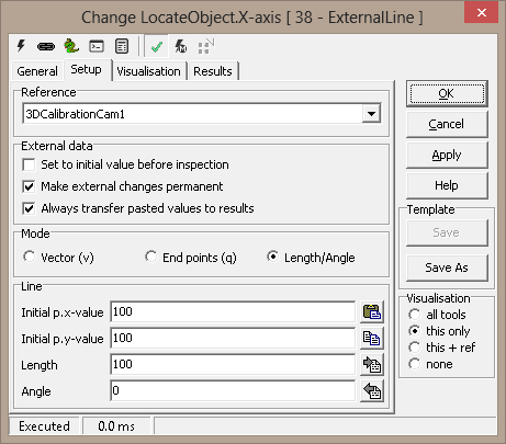
1. The ‘Reference’ drop down can be used to select the
input 2D reference. The input 2D reference provides the origin (0,0) and
rotation of the X and Y-axis. It is strongly recommended to click on the
'Apply' button available on the main tool configuration window, to apply the
newly selected input reference. This reference is then used while
configuring all other tool parameters.
2. The ‘External data’ group can be used for defining the
properties for the line.
3. The ‘Set to initial value before inspection’ check-box
can be used to reset the value of line,
to the configured initial value, before every inspection cycle.
4. The ‘Make external changes permanent’ check-box can be
used to make the value persistent, which means that the value of the state
is remembered across the session. The last value if remembered when the
profile is closed and the value of the tool is reset to this remembered
value when the profile is loaded next time.
5. The ‘Always transfer pasted values to results’ check-box can be
used to immediately transferring all the pasted values to results when the
'Paste ROI from Clipboard' button is clicked.
6. The 'Mode' group can be used to select appropriate mode
for configuring the initial values for the line.
7. The 'Vector (v)' option can be selected to configure the
initial values for the line as a start point and a vector - x and y
coordinates of the start point, and x and y coordinates representing a
vector, where all values are floating point values.
8. The 'End points (q)' option can be selected to configure
the initial values for the line as a start point and an end point - x and y
coordinates of the start point, and x and y coordinates of the end point,
where all values are floating point values.
9. The 'Length/Angle' option can be selected to configure
the initial values for the line as a start point and a length value and an
angle value - x and y coordinates of the start point, and length and angle
of the line, where all values are floating point values, and the angle is in
degrees.
10. The 'Line' group user interface elements change as per
the selected mode. The default mode is the 'End points (q)' mode.
11. The ‘Initial p.x-value’ text-box can be used to specify
the initial value of the x coordinate of the start point of the line. It can be any
floating point value.
12. The ‘Initial p.y-value’ text-box can be used to specify
the initial value of the y coordinate of the start point of the line. It can be any
floating point value.
13. The ‘Initial q.x-value’ text-box can be used to specify
the initial value of the x coordinate of the end point of the line. It can be any
floating point value.
14. The ‘Initial q.y-value’ text-box can be used to specify
the initial value of the y coordinate of the end point of the line. It can be any
floating point value.
15. The 'Line' group user interface elements change as per
the selected mode. When the mode is set to 'Vector (v)', the user interface
elements change.
16. The ‘Initial p.x-value’ text-box can be used to specify
the initial value of the x coordinate of the start point of the line. It can be any
floating point value.
17. The ‘Initial p.y-value’ text-box can be used to specify
the initial value of the y coordinate of the start point of the line. It can be any
floating point value.
18. The ‘Initial v.x-value’ text-box can be used to specify
the initial value of the x coordinate of the line vector. It can be any
floating point value.
19. The ‘Initial v.y-value’ text-box can be used to specify
the initial value of the y coordinate of the line vector. It can be any
floating point value.
20. The 'Line' group user interface elements change as per
the selected mode. When the mode is set to 'Length/Angle', the user
interface elements change.
21. The ‘Initial p.x-value’ text-box can be used to specify
the initial value of the x coordinate of the start point of the line. It can be any
floating point value.
22. The ‘Initial p.y-value’ text-box can be used to specify
the initial value of the y coordinate of the start point of the line. It can be any
floating point value.
23. The ‘Length’ text-box can be used to specify the length
of the line segment. It can be any
floating point value.
24. The ‘Angle’ text-box can be used to specify the angle
of the line. It can be any
floating point value. Angle is in degrees.
25. The ‘Paste ROI from Clipboard’ button can be used to
copy user defined line from the clipboard to the initial value properties.
It is expected that a single line is defined on the image, by pressing the
CTRL keyboard key and simultaneously using mouse left button click to define
the target points which indicate the selected line. When ‘Paste ROI from Clipboard’ button is clicked, the
coordinated of this selected line are copied to the line initial values text-boxes, considering the configured input 2D reference.
Please note that if the input 2D reference is changed, it is required to
again click on the 'Paste ROI from Clipboard' to paste correct coordinates
of the selected line, as per the new input 2D reference.
If more than 2 points are selected on the image, which indicate a polygon,
clicking on the 'Paste ROI from Clipboard' button has no effect. It is
expected that only 2 points indicating a line are selected on the image while 'Paste ROI
from Clipboard' button is clicked for pasting the coordinates of the
selected line.
If only single point is selected on the image, clicking on the 'Paste ROI
from Clipboard' button updates the coordinates of the start point of the
line, keeping other values unchanged.
When 'Paste ROI from Clipboard' button is clicked, the mode is automatically
reset to the 'Length/Angle' mode.
26. The ‘Copy ROI to Clipboard’ button can be used
to paste the configured line to the clipboard. This is useful in
viewing the exact location of the configured line on the inspection image and
fine-tuning, if required.
When 'Copy ROI to Clipboard' button is clicked, the mode is automatically
reset to the 'Length/Angle' mode.
27. The ‘Transfer initial value to result’ button can be
used to set the result of the tool to the configured initial value. The
result value of the tool does not get updated, unless processing happens. It
is a recommended practice to click this button to set the result value to
the initial value during the ExternalLine tool configuration.
28. The ‘Transfer results to initial value’ button can be
used to set the initial value of the tool to the current tool result value.
Basic Processing when the tool is executed:
1. If 'Set to initial value before inspection' is enabled,
the value of the state held by the tool is reset to the configured 'initial
value'.
|
Inputs to the Tool: |
| Inputs: |
None |
| Uses Reference: |
Yes, uses a 2D reference |
| Uses Image: |
No |
| |
|
|
Outputs from the Tool: |
| Outputs: |
|
1 |
Value_p_x: |
Numeric |
The current value of
the x
coordinate
of the start
point of the
line. This
is a
floating
point value. |
|
2 |
Value_p_y: |
Numeric |
The current value of
the y
coordinate
of the start
point of the
line. This
is a
floating
point value. |
|
3 |
Value_v_x: |
Numeric |
The current value of
the x
coordinate
of the line
vector. This
is a
floating
point value. |
|
4 |
Value_v_y: |
Numeric |
The current value of
the y
coordinate
of the line
vector. This
is a
floating
point value. |
|
5 |
Value_q_y: |
Numeric |
The current value of
the y
coordinate
of the end
point of the
line. This
is a
floating
point value. |
|
6 |
Value_q_y: |
Numeric |
The current value of
the y
coordinate
of the end
point of the
line. This
is a
floating
point value. |
|
7 |
Value_Length: |
Numeric |
The current
length of
the line. This
is a
floating
point value. |
|
8 |
Value_Angle: |
Numeric |
The current
angle of the
line. This
is a
floating
point value. |
|
9 |
StatusText: |
Text |
This is a
standard
output from
all Scorpion
tools and
describes
the
processing
status |
|
10 |
Status: |
Numeric |
This is a
standard
output from
all Scorpion
tools and
indicates
error/success
of the tool
processing.
1 indicates
success and
0 indicates
error. |
|
11 |
AnalyzeTime: |
Numeric |
This is a
standard
output from
all Scorpion
tools and
indicates
the time
taken by the
last
processing
operation of
this tool |
|
| Visualizations: |
|
1 |
Value: |
Displays
the line as
per the
current
values |
|
| Reference outputs: |
None |
| |
|
|
Templates: |
| Supports Templates: |
No |
| |
|
