|
Scorpion Vision Software supports Matrox Iris GT smart camera family using the
The following cameras are tested and verified
The driver will also support other area scan cameras connected using MIL
9.0 interface.
Prerequisites
- Scorpion Vision Software version 8 or higher
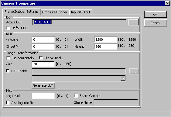
Property Pages: Frame Grabber
-
Active DCF
The user has to select valid DCF file. If 'Default' DCF is selected, then DCF specified by Matrox Mil setup will be used.
-
Offset X
This value sets the X offset (left offset) for the area of interest in pixels, i.e., the distance in pixels between the left side of the sensor and the left side of the image area.
-
Offset Y
This value sets the Y offset (top offset) for the area of interest, i.e., the distance in pixels between the top of the sensor and the top of the image area.
-
Width
This value sets the width of the area of interest in pixels.
-
Height
This value sets the height of the area of interest in pixels.
-
Flip horizontally
Flip the image horizontally.
-
Flip vertically
Flip the image vertically.
-
Gain
-
LUT
Apply lookup table. Lookup table must follow some rules, see
example. In drop down list choose column to
use.
-
Generate LUT
Logarithmic LUT table generation.
-
Log level
Level 0 suppresses all messages.
Level 1 issues error and warning messages.
Levels 2,3,4 issue diagnostic messages. Beware that level 4 produces a
lot of messages therefore should be used only on small size images for
diagnostic purposes only.
- Also log into file.
Write camera related messages into log file. Normally messages are
written only on Scorpion console, provided console is enabled for camera
messages.
Logarithmic LUT table generation
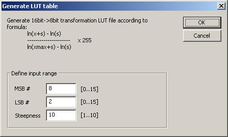
- MSB #
Most significant bit.
- LSB #
Least significant bit.
-
Steepness
Steepness parameter s.
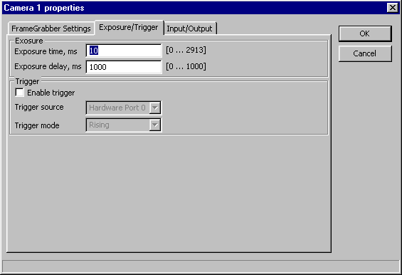
Property Pages: Exposure/Trigger
-
Exposure time
Set active portion time of exposure in milliseconds.
-
Exposure delay
Set delay before active portion of the exposure in milliseconds.
-
Enable tigger
Set grab trigger detection state.
-
Trigger source
Set the source of the grab trigger:
-
Trigger mode
Set hardware trigger activation mode:
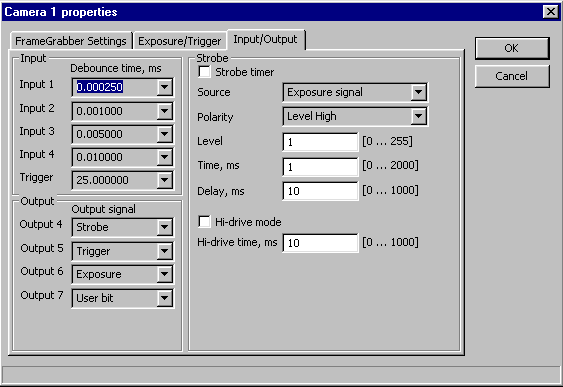
Property Pages: Input/Output
-
Debounce time
Set the debounce time applied to input signal number 0 to 3 and the trigger.
-
Output signal
Set the type of signal routed to an auxiliary output signal.
-
Strobe timer
Enable the strobe timer.
-
Source
Set the source of the strobe output signaling:
- Exposure signal - the strobe signal generation will be synchronized with the exposure signal
- Trigger signal - the strobe signal generation will be synchronized with the trigger signal
-
Polarity
Set polarity of the active portion of the strobe signal:
-
Level
Set strobe PMW level. The possible values are from 0 for 0.4% PWM to 255 for 100% PWM.
-
Time
Set active portion time of strobe in milliseconds.
When the trigger signal used for the strobe signal generation, sets the length of
strobe active period while the exposure signal is active.
-
Delay
Set delay before active portion of the strobe in milliseconds.
When the trigger signal used for the strobe signal generation, sets the delay to use
between trigger and start of strobe signal.
-
Hi-drive mode
To activate or not strobe PWM first period level in hi-drive mode.
-
Hi-drive time
Set strobe PWM first period hi-drive time in milliseconds.
ExecuteCmd support
|
Command
|
Parameters
|
Return values
|
Comments
|
|
MdigControl |
ControlType=<number>;
ControlValue=<number> |
ok,None |
Allows you to control various digitizer settings. See MIL reference manual. |
Camera Property Access from python scripts
The following properties can be accessed via
'setProperty' and 'getProperty' commands:
- 'Continuous'
- 'Exposure'
- 'ExposureDelay'
- 'Gain'
- Input signals:
- 'UserBit0'
- 'UserBit1'
- 'UserBit2'
- 'UserBit3'
- Output signals:
- 'UserBit4'
- 'UserBit5'
- 'UserBit6'
- 'UserBit7'
|
