|
Scorpion Vision software supports SVS-VISTEK ECO family GigE cameras:
Prerequisites
-
Scorpion Vision Software version 8.0.0.441 or higher
- SVCam GigE
SDK installed
- Cameras are configured and detected by SVCapture
Note: There are some issues
with SVS when setting trigger signal to strobe. Our tests reveal that to
start using Strobe signals, StrobePosition must be changed from positive to negative and back
to the initial (or vice versa). It depends on TriggerPolarity - both parameters must be
either positive or negative.
Python set/getProperty can be used to perform that inside Scorpion profile.
General
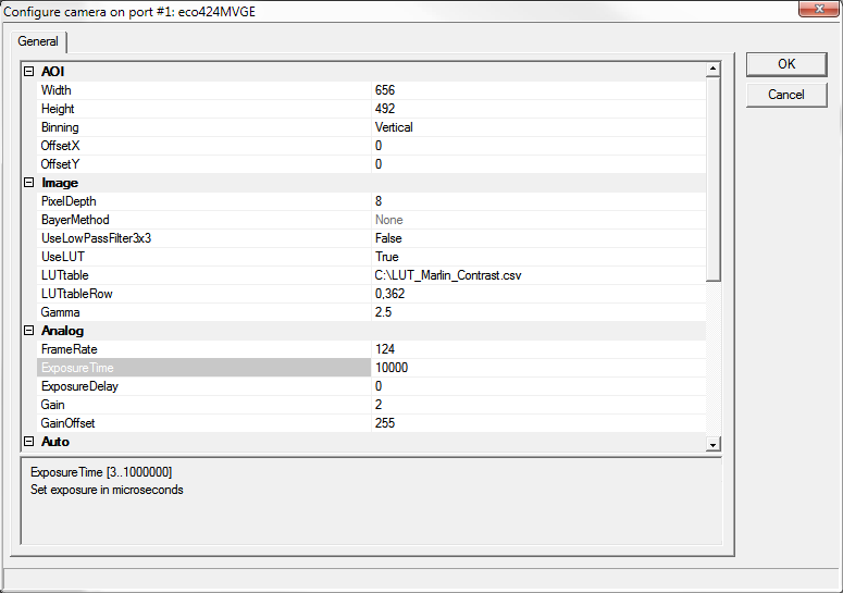
The following properties are available:
- AOI
- Width
This value sets the width of the area of interest in pixels.
- Height
This value sets the height of the area of interest in pixels.
- Binning
The camera can be set to one of the following binning modes:
- 0 - Off.
- 1 - Horizontal.
- 2 - Vertical.
- 3 - 2x2.
- OffsetX
This value sets the X offset (left offset) for the area of interest in pixels, i.e.,
the distance in pixels between the left side of the sensor and the left side of the image area.
- OffsetY
This value sets the Y offset (top offset) for the area of interest, i.e.,
the distance in pixels between the top of the sensor and the top of the image area.
- Image
- PixelDepth
The number of bits for a pixel (implemented 8bit).
- bayerMethod
The image will be converted by a selectable Bayer conversion algorithm into a RGB image.
Supports only color cameras.
- -1 - None.
- 1 - Simple.
- 3 - HQLinear.
- UseLowPassFilter3x3
A filter which smoothes an image inside a camera accordingly to a given algorithm 3x3.
Supports only monochrome cameras.
- UseLUT
This feature activates LUT (look-up table).
- LUT
Apply lookup table. Lookup table must follow some rules, see an
example.
- LUTtableRow
Select a column name, provided by LUTtable text file.
- Gamma
This feature is used to perform gamma correction of pixel intensity (active when UseLUT is disabled).
- Analog
- FrameRate
Configure the frame rate manually. However, you cannot increase the frame rate beyond the fastest settings. In addition, if the exposure time is longer than the configured frame period, the frame rate will be reduced in proportion to the exposure time.
When you want to minimize network traffic, use this setting to lower the frame rate while maintaining the same shutter setting.
- ExposureTime
This feature used to set the Exposure time (in us).
- ExposureDelay
The camera's exposure delay in micro seconds relative to the trigger pulse will be set to the provided value. The delay will become active each time an active edge of an internal or external trigger pulse arrives.
- Gain
This feature used to set analog gain (in db).
- GainOffset
The offset value for pixel will be set to the provided value (0..255).
- Auto
- UseAutoGain
This feature activates automatic gain control.
- AutoGainBrightness
The target brightness (0..255) will be set which the camera tries to reach automatically when auto gain/exposure is enabled. The range 0..255 always applies independently from pixel depth.
- AutoGainLimitMin
The minimal gain will be determined that the camera must not exceed in auto gain mode.
- AutoGainLimitMax
The maximal gain will be determined that the camera must not exceed in auto gain mode.
- AutoExposureLimitMin
The minimal gain will be determined that the camera must not exceed in auto exposure mode.
- AutoExposureLimitMax
The maximal gain will be determined that the camera must not exceed in auto exposure mode.
- Acquisition
- AcquisitionMode
The camera's acquisition mode will be set to the selected value:
- 1 - Fixed frequency.
- 2 - Software trigger.
- 3 - External trigger / Internal exposure.
- 4 - External trigger / External exposure.
- TriggerInput
The camera's trigger line input will be set to the selected value:
- 1 - None
- 2 - IN1.
- 4 - IN2.
- 8 - IN3(RS422).
- 16 - RXD(RS232).
- 64 - Strobe.
- Output1
The camera's trigger line input will be set to the selected value:
- 1 - None.
- 2 - IN1.
- 4 - IN2.
- 8 - IN3(RS422).
- 16 - RXD(RS232).
- 64 - Strobe.
- 128 - FixedLow.
- 256 - FixedHigh.
- Output2
The camera's trigger line input will be set to the selected value:
- 1 - None.
- 2 - IN1.
- 4 - IN2.
- 8 - IN3(RS422).
- 16 - RXD(RS232).
- 64 - Strobe.
- 128 - FixedLow.
- 256 - FixedHigh.
- Output3(RS422)
The camera's trigger line input will be set to the selected value:
- 1 - None.
- 2 - IN1.
- 4 - IN2.
- 8 - IN3(RS422).
- 16 - RXD(RS232).
- 64 - Strobe.
- 128 - FixedLow
- 256 - FixedHigh
- TXD(RS232)
The camera's trigger line input will be set to the selected value:
- 1 - None.
- 2 - IN1.
- 4 - IN2.
- 8 - IN3(RS422).
- 16 - RXD(RS232).
- 64 - Strobe.
- 128 - FixedLow.
- 256 - FixedHigh.
- TriggerPolarity
A camera can be set to positive or negative trigger polarity:
- 0 - Positive.
- 1 - Negative.
- StrobePolarity
A camera can be set to positive or negative strobe polarity:
- 0 - Positive.
- 1 - Negative.
- StrobePosition
The camera's strobe position in micro seconds relative to the trigger pulse.
- StrobeDuration
The camera's strobe duration in micro seconds.
- Logging
- LogLevel
- Level 0 suppresses all messages.
- Level 1 issues error and warning messages.
- Levels 2,3,4 issue diagnostic messages.
- Beware that level 4 produces
a lot of messages therefore should be used only on small size images
for diagnostic purposes only.
- LogIntoFile
Write camera related messages into log file. Normally messages are written only on Scorpion console, provided console is enabled for camera messages.
Note: Setting is not stored in configuration and will be turned off on restart.
Properties available from Python
The following named properties can be dynamically accessed with 'setProperty' command:
- 'continous'
- 'reset'
- 'gamma'
- 'framerate'
- 'exposuretime'
- 'exposuredelay'
- 'gain'
- 'gainOffset'
- 'strobepolarity'
- 'triggerpolarity'
- 'loglevel'
- 'logdebugview'
All properties can be dynamically accessed with 'getProperty' command.
Example 1: Start Continuous grabbing
GetCamera('0').setProperty('continuous', 1)
Example 2: Stop Continuous grabbing
GetCamera('0').setProperty('continuous', 0)
Example 3: set/get camera property
  GetCamera('0').setProperty('framerate',
30)

  print GetCamera('0').getProperty('frameRate')
|
