|
Scorpion Vision Software supports Pylon interface to Basler GigE and Firewire cameras:
- PylonAreaCamera.dll
- for GigE cameras
- PylonAreaCamera1394.dll
- for firewire cameras
The following Pylon versions are supported:
- Pylon 4.0
- Pylon 2.3
- Pylon 2.2
- Pylon 2.1
See Scorpion Installer for Pylon installation.
This interface is supported with Scorpion Vision Software 7 or higher
version number.
The release notes page provide to all
Scorpion Camera Drivers available with reference to the corresponding Pylon
version.
The GigE cameras are configured and detected by IP Config and
Pylon Viewer. It is important to make sure that IP addresses of cameras and interfaces are correctly assigned.
Test and deployment status
The drivers was initially developed in the spring of 2010. It has now been
stable and running in production systems for quite a while.
- The driver has been tested on the Ace
and Scout series.
- The firewire drivers has been
tested on the Scout Series.
- Both Color and Monochrome cameras are supported.
Bandwidth control
In order for cameras to function properly make sure the bandwidth is properly configured. When cameras are running in a free
run mode there are some items to take into consideration. The driver internaly runs at a framerate specified in camera properties
even if the scorpion is triggering at much slower pace. There are several properties that affect camera frame rate. They are:
- Exposure time - When "Enable Acquisition Frame Rate" is not checked camera will stream images as fast as it can with a set exposure.
- Enable Acquisition Frame Rate - Enables framerate control
- Acquisition Frame Rate - Defines max number of images to deliver in one second ("Enable Acquisition Frame Rate" must be checked)
When calculating bandwidth take into consideration that camera driver internaly will be running at a speed defined in camera properties but not at a
speed Scorpion requests for an image. So if you want to reduce used bandwidth, set camera frame rate to a desired value.
Using software trigger
In order to use camera software trigger following must be done:
- Trigger source must be set to "Software"
- To issue trigger execute command "Grab" (python example: ExecuteCmd('Grab','') or via Scorpion actions)
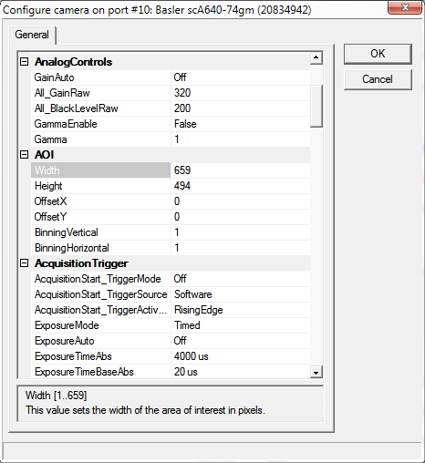
General
Note: only explicitly modified parameters are saved. This allows to choose between alternatives parameters, for example ExposureTimeRaw or ExposureTimeAbs.
The following properties are available:
- ImageFormat
- UseBGR
This should be enabled for color cameras, otherwise blue and red will be
swapped in the final image.
- TestImageSelector
This enumeration provides a list of the available test images. Selecting a test image from the list will enable the test image.
- AnalogControls
- GainAuto
The gain auto function automatically adjusts the Auto Gain Raw parameter value within set limits,
until a target average gray value for the pixel data from Auto Function AOI1 is reached.
- All_GainRaw
Sets the 'raw' value of the selected gain control. The 'raw' value is an integer value that sets the selected
gain control in units specific to the camera.
- All_BlackLevelRaw
This value sets the black level control.
- GammaEnable
Enables the gamma correction.
- Gamma
This feature is used to perform gamma correction of pixel intensity.
- AOI
- Width
This value sets the width of the area of interest in pixels.
- Height
This value sets the height of the area of interest in pixels.
- OffsetX
This value sets the X offset (left offset) for the area of interest in pixels, i.e.,
the distance in pixels between the left side of the sensor and the left side of the image area.
- OffsetY
This value sets the Y offset (top offset) for the area of interest, i.e.,
the distance in pixels between the top of the sensor and the top of the image area.
- BinningVertical
Sets the number of binned adjacent vertical pixels. Their charges will be summed and reported out of the camera as a single pixel.
- BinningHorizontal
Sets the number of binned adjacent horizontal pixels. Their charges will be summed and reported out of the camera as a single pixel.
- AcquisitionTrigger
- TriggerMode
This enumeration sets the trigger mode for the selected trigger.
- TriggerSource
This enumeration sets the signal source for the selected trigger.
- TriggerActivation
This enumeration sets the signal transition needed to activate the selected trigger.
- ExposureAuto
The exposure auto function automatically adjusts the Auto Exposure Time Abs parameter value within set limits,
until a target average gray value for the pixel data of the related Auto Function AOI is reached.
- ExposureTimeRaw
This value sets an integer that will be used as a multiplier for the exposure timebase.
The actual exposure time equals the current exposure time raw setting times the current exposure time base abs setting.
- ExposureTimeAbs
This float value sets the camera's exposure time in microseconds.
- ExposureTimeBaseAbs
This float value sets the time base (in microseconds) that is used when the exposure time is set with the 'raw' setting.
- AcquisitionFrameRateEnable
This boolean value enables setting the camera's acquisition frame rate to a specified value.
- DigitalIO
- LineX_LineMode
This feature controls whether the physical Line is used to Input or Output a signal.
When a Line supports input and output mode, the default state is Input to avoid possible electrical contention.
Line Mode can take any of the following values:
- Input: The selected physical line is used to input an electrical signal.
- Output: The selected physical line is used to output an electrical signal.
- LineX_LineDebouncerTimeRaw
Sets the raw value of the selected line debouncer time
- LineX_LineFormat
This feature controls the current electrical format of the selected physical input or output Line.
Line Format can take any of the following values:
- No Connect: The Line is not connected.
- Tri-state: The Line is currently in Tri-state mode (Not driven).
- TTL: The Line is currently accepting or sending TTL level signals.
- LVDS: The Line is currently accepting or sending LVDS level signals.
- RS-422: The Line is currently accepting or sending RS-422 level signals.
- Opto-coupled: The Line is Opto-coupled.
- OutX_LineInverter
This boolean value enables the inverter function for the selected line.
- OutX_LineStatus
This boolean value indicates the current logical state for the selected line at the time of polling.
- OutX_LineSource
This enumeration selects the internally generated camera signal (source signal) for the selected line.
- OutX_UserOutputValue
This boolean value sets the state of the selected user settable output signal.
- TimerControls
- TimerDurationTimebaseAbs
This float value sets the time base (in microseconds) that is used when a timer duration is set with the 'raw' setting.
- TimerDelayTimebaseAbs
This float value sets the time base (in microseconds) that is used when a timer delay is set with the 'raw' setting.
- TimerX_TimerDelayRaw
This value sets an integer that will be used as a multiplier for the timer delay timebase.
The actual delay time equals the current timer delay raw setting times the current timer delay time base abs setting.
- TimerX_TimerDurationRaw
This value sets an integer that will be used as a multiplier for the timer duration timebase.
The actual duration time equals the current timer duration raw setting times the current timer duration time base abs setting.
- TimerX_TimerTriggerSource
This enumeration sets the internal camera signal used to trigger the selected timer.
- TransportLayer
- GevHeartbeatTimeout
This value sets the heartbeat timeout in milliseconds.
- StreamChannel0_GevSCPSPacketSize
If using other packet size than default (1500), unless you have already
set the packet size for your network adapter during the installation of
the Pylon AreaScan software, check the documentation for your adapter to determine
the maximum packet size (sometimes called “frame” size) that the adapter can handle. Many
adapters can handle what
is known as “jumbo packets” or "jumbo frames". These are packets with a
maximum size of 16 kB.
Once you have determined the maximum size packets the adapter can handle,
make sure that the adapter is set to use the maximum packet size.
- StreamChannel0_GevSCPD
Sets delay in ticks between packets
sent by the camera. Applies to the selected stream channel.
Increasing the inter-packet delay will decrease the camera's
effective data transmission rate and will thus decrease the network
bandwidth used by the camera. In the current camera implementation,
one tick=8ns.
- StreamChannel0_GevSCFTD
Sets a delay in ticks (one tick
= 8 ns) between when a camera would normally begin transmitting an
acquired frame and when it actually begins transmission. This
parameter should be set to zero in most normal situations. If you
have many cameras in your network and you will be simultaneously
triggering image acquisition on all of them, you may find that your
network switch or network adapter is overwhelmed if all of the
cameras simultaneously begin to transmit frame data at once. The
frame transmission delay parameter can be used to stagger the start
of frame data transmission from each camera.
- StreamChannel0_GevSCBWR
Used to reserve a portion of the
assigned bandwidth for packet resends and for the transmission of
control data between the camera and the host PC. The setting is
expressed as a percentage of the Bandwidth Assigned parameter. For
example, if the Bandwidth Assigned parameter indicates that 30
MByte/s have been assigned to the camera and the Bandwidth Reserve
parameter is set to 5%, then the bandwidth reserve will be 1.5
MByte/s.
- StreamChannel0_GevSCBWRA
A software device called
the bandwidth reserve accumulator is designed to handle unusual
situations such as a sudden EMI burst that interrupts a frame
transmission. If this happens, a larger than normal number of packet
resends may be needed to properly transmit a complete frame. The
accumulator is basically an extra pool of resends that the camera
can use in unusual situations.
- StreamChannel0_GevSCBWA(read-only)
Indicates the bandwidth in bytes per
second that will be used by the camera to transmit frame and chunk
feature data and to handle resends and control data transmissions.
The value of this parameter is a result of the packet size and the
inter-packet delay parameter settings.
Note: Sum of
bandwidth for all cameras on the same NIC must not exceed 125MB/s on
a gigabit network. Otherwise frame overruns may occur.
- StreamChannel0_GevSCDCT(read-only)
Indicates the actual bandwidth (in
bytes per second) that the camera will use to transmit the image
data and chunk data (if any) in each frame given the current frame
size, chunk feature settings, and the pixel format setting.
- StreamChannel0_GevSCFJM(read-only)
If the Bandwidth Reserve Accumulation
parameter is set to a high value, the camera can experience a large
burst of data resends during transmission of a frame. This burst of
resends will delay the start of transmission of the next acquired
frame. The Frame Max Jitter parameter indicates the maximum time in
ticks (one tick = 8 ns) that the next frame transmission could be
delayed due to a burst of resends.
- AutoFunctions
- AutoTargetValue
The target average gray value may range from nearly black to nearly white.
Note that this range of gray values applies to 8 bit and to 16 bit (12 bit effective) output modes.
Accordingly, also for 16 bit output modes, black is represented by 0 and white by 255.
- AutoGainRawLowerLimit
Lower limit of the Auto Gain (Raw) parameter
- AutoGainRawUpperLimit
Upper limit of the Auto Gain (Raw) parameter
- General
- Log level.
- Level 0 suppresses all messages.
- Level 1 issues error and warning messages.
- Levels 2,3,4 issue diagnostic messages. Beware that level 4 produces a
lot of messages therefore should be used only on small size images for
diagnostic purposes only.
- Also log into file.
Write camera related messages into log file. Normally messages are
written only on Scorpion console, provided console is enabled for camera
messages.
- InhibitPylonTerminate.
If enabled Pylon - terminate function will not be called. Enable when using several pylon drivers in the same profile, for example Basler Runner together with Area Scan gige or firewire cameras.
Camera Property Access from python scripts
The following named properties
can be dynamically accessed with 'SetProperty' or 'GetProperty' commands from
within Scorpion Vision Software:
- 'continuous'
Enter or leave continuos grabbing mode. This parameter cannot be set via gui page.
- 'Exposure'
- 'Gain'
|
