|
Scorpion Vision Software supports Sony GigE
- XCG-V60E
- XCG-SX97E
- XCG-U100E
- XCG-5005E
The Sony datasheet can be downloaded
here...
cameras using the
- SonyXCGCamera.dll - Scorpion Camera Driver
The driver has been tested under XP Embedded, XP, and Windows 7.
Works only for 32 bit Windows. 64 bit operation system
support provided by ZCL driver.
Prerequisites
- Scorpion Vision Software version 7 or higher
- XCG-software
package installed.
- Cameras are configured and detected by XCG-Software
Note:
- When camera property page is closed the camera becomes inactive for some duration (up to 30 seconds),
then camera gets active again. This is expected behaviors.
- Verify that the network adapter
package size matches the size of the camera
- Width and Offset parameters both influence maxWidth
value. When Offset or Width is decreased, the maxWidth will
be updated only upon next open of properties dialog. The
same goes for Height/heightOffset parameters.
- Do not set log levels higher then 1
when running in production.
- Driver and software is available
under Release Notes
- Fixed IP
require allocating them in the
auto-configuration IP range: 169.254.x.x with subnet masks
255.255.0.0.
- Both ZCL
and XCG driver can be installed on the same PC but only one
filter driver can be active at the same time.
- Simply uncheck either the Sony
Filter Driver or ZCL Filter Driver from the
adapter's properties window to
enable/disable one or the other.
Example profile can be downloaded here...
Configuration notes
- Manage Bandwidth
- It is important that the total bandwidth used by cameras does not exceed the
bandwidth capability of the network adaptor. The total bandwidth of a Gigabit Ethernet network adaptor is about 120 million bytes per second.
- Bandwidth Calculation =
Height * Width * Refresh rate
* No Of Cameras
- Bandwidth Calculation
Example - 4 MPixel Camera
- The Image size is 2048x2048 and refresh rate 10 frames per second, the used bandwidth
will be
- 2048 * 2048 * 10 =
41943040 bytes/s = 42MB/s/camera
- With this configuration
on the same network adaptor can be connected no
more than two cameras.
- Hint 1: Trigger Delay
- Triggering multiple cameras at the same time may result in collision in the network and
the camera may
return an error.
- The solution for this might be to use trigger delay. For the second camera
set 'TriggerDelay' parameter in the properties dialog to 100000 microseconds.
- Hint 2: Jumbo Frames
- If network card supports Jumbo frames, you should set this number to be
at least 9000 kB when configuring your network card settings. Set the 'PacketSize'
parameter in the Properties dialog to match the maximum Jumbo packet size.
Property page
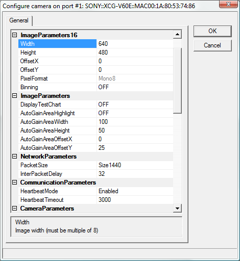
Note:
Names of parameters are retrieved from camera via genicam and may
change with new camera firmware version. The exact name to be used in
scripting can always be looked up from the dialog (above).
- Width
Image width in pixels. Must be multiple of 8.
- Height
Image height in pixels. Must be multiple of 4.
- OffsetX
Horizontal offset in pixels.
- OffsetY
Vertical offset in pixels.
- PixelFormat
Pixel format.
- BinningVertical
This mode increases sensitivity and frame rate by combining vertically adjacent pixel data from the CCD.
Binning mode approximately doubles sensitivity by combining vertical signals on alternate pairs of adjacent lines.
However, because the frame rate is also doubled, available exposure time is consequently halved. Setting a shorter
exposure time enhances the effect, and sensitivity is further increased. Consider the effect on exposure time when using
the Binning mode.
- AcquisitionFrameRateAbs
Configure the frame rate manually. However, you
cannot increase the frame rate beyond the fastest
setting. In addition, if the exposure time is longer than
the configured frame period, the frame rate will be
reduced in proportion to the exposure time.
When you want to minimize network traffic, use this
setting to lower the frame rate while maintaining the
same shutter setting.
- AcquisitionFrameRateAuto
The fastest frame rate is configured automatically
based on the current shutter setting and binning/partial
scan setting.
To increase the frame rate, enable the binning mode or
partial scan function. Depending on whether the
exposure time is longer than the frame period, the
frame rate will be reduced proportionally. Therefore,
shorten the shutter time as necessary.
- TriggerMode
TriggerMode define if the selected trigger is active.
- TriggerSourceSelect
TriggerSource specifies the internal signal or physical
input Line to use as the trigger source for the selected
trigger when TriggerMode is On.
- TriggerInhibit
This function disables the camera’s trigger input.
When multiple cameras are connected, use this to
disable triggering for only specified cameras at specific
times.
- TriggerActivation
This function selects whether triggering occurs at the
rising or falling edge of the trigger signal.
- TriggerOverlap
TriggerOverlap specifies the type trigger overlap permitted with the previous frame.
- TriggerDelayRaw
This function applies a trigger delay within the camera.
Use it to synchronize trigger timing when the trigger
signal is offset from the desired object exposure timing.
- ExposureTimeRaw
This feature used to set the Exposure time (in us) when ExposureMode is Timed.
- Gamma
This feature is used to perform gamma correction of pixel intensity.
- GammaLowLevel
This feature is used to perform black level setting of Gamma (in 12 bits).
- BinarizationThreshold
This feature controls the binarization threshold (in 12 bits).
- GainSelector
This feature selects which Gain is controlled by the various Gain features.
- GainRaw
This feature controls the selected gain as a raw integer value (in step).
- GainAbs
This feature controls the selected gain as an absolute physical value (in dB).
- GainAuto
This feature performs automatic gain control (AGC).
- GainAutoLevel
This feature is used to perform luminance level setting of automatic gain control (in 14 bits).
- BlackLevelSelector
This feature selects which Black Level is controlled by the various Black Level features.
- BlackLevelRaw
This feature controls the digital black level as a raw integer value (in 14 bits).
- LineSelector
This feature selects which physical line (or pin) of the external device connector to configure.
- LineMode
This feature controls if the physical Line is used to Input or Output a signal.
- LineInverter
This feature controls if the electrical output signal on the selected Line is inverted.
- LineStatus
This feature read the current status of the input Line.
- LineSource
This feature is used to select which internal acquisition or I/O source signal to output (TTL) on the selected Line when its LineMode is Output.
- LineFormat
This feature returns the current electrical format of the selected physical output Line.
- UserOutputSelector
This feature selects which bit of the User Output register will be set by UserOutputValue.
- UserOutputValue
This feature sets the value of the selected bit of the User Output register.
- StrobeActiveTimeRaw
This feature used to set the Strobe active time (in us).
- StrobeActiveDelayRaw
StrobeActiveTimeRaw specifies the delay (in us) to apply after the StrobeActive before effectively activating it.
- TestImageSelector
This feature selects the type of test image that is sent by the camera.
- GainAutoAreaHighlight
This feature activates the detection area highlight of automatic gain control.
- GainAutoAreaWidth
This feature represents the actual detection area width expelled by the camera (in percent).
- GainAutoAreaHeight
This feature represents the actual detection area height expelled by the camera (in percent).
- GainAutoAreaOffsetX
This feature represents the horizontal offset of the actual detection area (in percent).
- GainAutoAreaOffsetY
This feature represents the vertical offset of the actual detection area (in percent).
- GevSCPSPacketSize
The stream packet size to send on this channel, except for data leader and data trailer, and the last data packet which might be of smaller size (since packet size is not necessarily a multiple of block size for stream channel).
- Log level
- Level 0 suppresses all messages.
- Level 1 issues error and warning messages.
- Levels 2,3,4 issue diagnostic messages.
- Beware that level 4 produces
a lot of messages therefore should be used only on small size images
for diagnostic purposes only.
-
Also log into file:
- Write camera related messages into log file. Normally messages are
written only on Scorpion console, provided console is enabled for
camera messages.
Note: Setting is not stored in configuration and will be turned off on restart.
Enable Hardware Trigger
Go to camera properties dialog and configure the following:
- Set 'Trigger' to 'ON'
- Set 'TriggerInhibit' to 'OFF'
- Select 'TriggerSource' value 'Hardware'
Note: the exact parameter naming may differ on different camera releases
Enable Software Trigger
Go to camera properties dialog and configure the following:
- Set 'Trigger' to 'ON'
- Set 'TriggerInhibit' to 'OFF'
- Select 'TriggerSource' value 'Software'
In Scorpion profile:
    cam = GetCamera('0')
    cam.setProperty('SoftwareTriggerSignal', 1)
Properties available from Python
The following named properties can be dynamically accessed with
the 'setProperty' and 'getProperty' commands:
- 'continuous'
- Enter or leave continuous grabbing mode. This parameter cannot be set via gui page.
- The continuous mode is normally set when using the command in
hw-trigger. Setting continuous modes removes the need for arming the
camera with a Grab command.
- 'Reset'
Close and Reopen the camera.
- 'ExposureTimeRaw'
- 'Gamma'
- 'GammaLevelLow'
- 'BinarizationThreshold'
- 'GainSelector'
- 'GainRaw'
- 'GainAbs'
- 'GainAuto'
- 'GainAutoLevel'
- 'BlackLevelSelector'
- 'BlackLevelSelectorReg'
- 'BlackLevelRaw'
- 'GainAutoAreaHighlight'
- 'GainAutoAreaWidth'
- 'GainAutoAreaHeight'
- 'GainAutoAreaOffsetX'
- 'GainAutoAreaOffsetY'
Example 1: Start Continuous grabbing
    cam = GetCamera('0')
    cam.SetProperty('continuous', 1)
Example 2: Stop Continuous grabbing
    cam = GetCamera('0')
    cam.setProperty('continuous', 0)
Example 3: Reset camera
    cam = GetCamera('0')
    cam.setProperty('Reset', 1)
Example
4: Set Shutter
    cam = GetCamera('0')
    cam.setProperty('ExposureTimeRaw', 250)
Example
5: Enable hardware triggering
    cam = GetCamera('0')
    cam.setProperty('TriggerMode', 1)
Example 5: Set white balance XCG-U100-CR
    def SetWhiteBalanceOnce():
      cam = GetCamera('0')
      cam.setProperty('0xA0003020', 1)
|
