|
PolygonMatch™ is
an optimal way to locate objects with sub-pixel accuracy independent of:
-
scale
-
rotation
-
size
-
perspective
-
skew
Multiple polygons
defines the shape or model of the object. Using the model the same shapes
are extracted from the images and fitted to the original model with the
highest possible accuracy.
The versatility of PolygonMatch™ makes it suitable for a large number
of applications:
- Robot Vision - pick and place
- 3D Stereo Vision
- Object Location
- Identification System
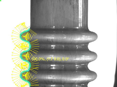
Below a valve which located using two polygons - a
circle and a straight line. A model can consist of any number of polygons.
The tool is very
powerful and
can be used to locate an object of any size or shape with sub-pixel resolution.
The next example corrects the location of a printed
circuit by 0.05 mm with accuracy better than
1/10 a pixel.
Other important application areas are shape verification.
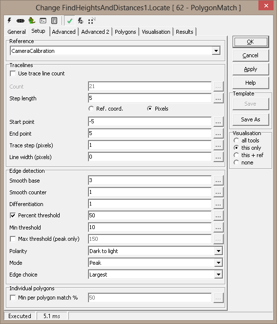
Setup
Reference - Reference system selection
Trace lines
-
Use Traceline Count - selects to specify the traceline count
-
Count - number of
trace lines
- Step length - distance between traceline
-
Start point - position of
starting point on trace line given in reference coordinates
- End point - position of
end point on trace line given in reference coordinates
- Inverted the sign of start
and stop point will change the direction of the trace comb
Trace step (pixels)
- normally 1 - given in pixels
Line width (pixels) - 0 - trace line is not averaged - a higher
value will average 2N+1 pixels perpendicular to the trace comb
Edge detection
- Smooth base - 3 is normally a good value
- Smooth counter - 1 default - given i pixels
- The smoothing increasing with higher values
- Differentiation
- 0 - give threshold
- 1 - 1. order differentiation - the derivative - default normally
used
- 2 - 2. order differentiation
- Threshold - the threshold or sensitivity of the edge detector -
a lower value increases the sensitivity
- Percent threshold activates adaptive - threshold is set to N % of maximum values of
edges
- Minimum treshold define minimum value of threshold to accept when
adaptive treshold is active
- Max threshold (peak only) - when active, peaks above this
value are ignored. The high peaks are also ignored when the percent
threshold is calculated.
- Polarity - All transitions | Light to dark | Dark to light
- Mode - Peak | Threshold
- Edge choice - First | Largest | Last | Nearest | First Nearest
| Largest Nearest
- Largest is
default and normally the best choice
Note: Combining adaptive threshold and first edge will help you
select the first strong edge
Individual polygons
- Min per polygon match % - when set, every polygon must have
at least this match. Normally this default is left off, and each polygon
gets an individual value (see the Polygons tab).
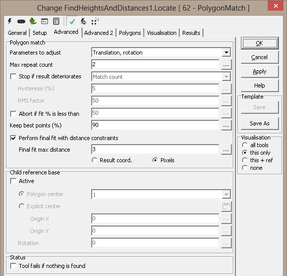
Advanced
Polygon match
-
Parameters to adjust
-
Translation, rotation - default
-
Translation, scale
-
Translation, rotation, scale, skew
-
Translation, rotation, perspective
-
Translation, rotation, scale
-
Max repeat count - the number of iteration
to fitting the polygons
-
Stop if result detteriorates - if the match
results get worse, the search is stopped. The quality measure of the
match can be the match percent, the RMS value or a combination of the
two.
-
Abort if fit % is less than - stops matching process if less than % edge
points is located - used to save time
-
Keep best points - the percentage of edge points
used in iteration
-
Perform final fit with distance constraints -
default on - added to be able to investigate polygon matching in detail
Child reference base
This sets the origin for the outgoing reference from the tool. The
reference is adjusted by the polygon fit results.
- Active - activate child reference base
- Polygon center - use the centerof gravity of the selected
model polygon
- Explicit center - set values
- Origin.X - X value
- Origin.Y - Y value
- Rotation - the base reference angle
Note : Child reference base is used to fix the model to the object
when needed
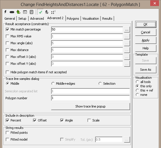
Advanced2
Result acceptance ( constraints )
-
Min match percentage - any of these
constraints may make a match invalid
-
Max RMS value
-
Max angle (abs)
-
Max distance
-
Max offsetX (abs)
-
Max offsetY (abs)
-
Hide polygon match items if not accepted -
only show polygons if a match is found
The result acceptance is reflected in the OK result -
can be used to easily validate the found polygon.
Trace line samples dialog - a helper window to set trace line
filter parameters and thresholds
- Middle - show the middle traceline
- Middle+edges - shows the first, middle and last traceline
- Selection - show the selected tracelines
- Line indices - traceline selection
- example: 2,3,12-15
- example: 1 3 5 7
-
- Show trace line popup - activates a modeless traceline window
Example tracelines - Middle+edges is selected
Include in description
Include in the onscreen description of valid/invalid match
- Percent
- Offset
- Angle
- Scale
String results
Create Python tuples describing the fitted model:
- Fitted points - the edge points
- Fitted model - the changed model
- Simplify - attempt to simplify the string.
- Tol (pix) - allow up to this deviation in the simplified
polygon
Matching a rectangle
A rectangle can be matched using PM.
This rectangle is matched using Rotation and
Translation. The angle is estimated correctly but the center of gravity is
moved due to the fact that the model is too long.
The same rectangle is matched using Translation,
Rotation and Scale. Both size, rotation and position is correctly and estimated
due to the fact that the model is fitted to the object.
The same rectangle is matched using Translation and Scale. The model is not accepted - the red rectangle is the original not
accepted model. The green rectangle is the fitted rectangle with size,
rotation and position errors.
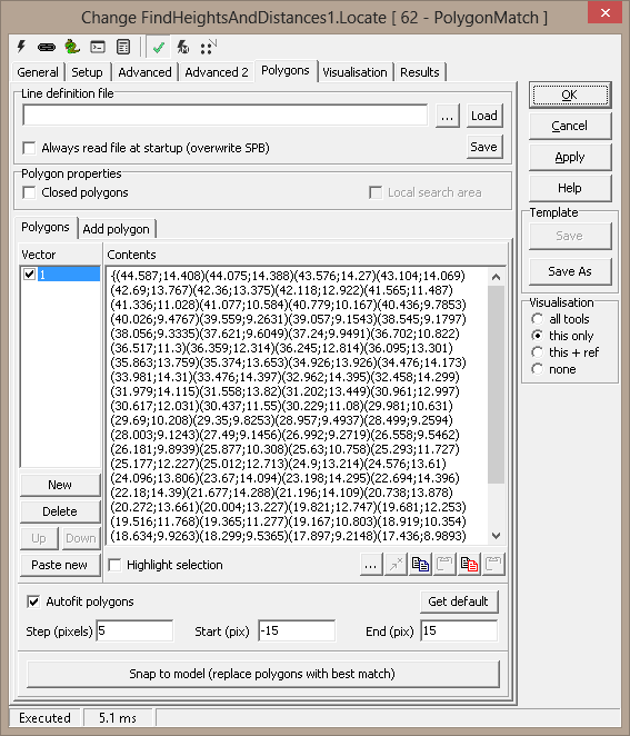
Polygons
Line definition file - The paths
to be searched are initially read from a text file (see the StrVec
format). The name of that file is also stored, for possible future
reload. The path information, however, is stored directly in the
system, without need for the external file.
You can browse for or manually edit the filename; by clicking
"Load", the file is read and its contents stored internally.
Polygon
properties
Polygon Editor
- Numbered list - ordered list of polygons. Each polygon can be
made active/inactive by clicking the checkbox in front of the number
- Contents - the points of the selected polygon
- New - add polygon
- Delete - remove selected polygon
- Up - moves polygon up in list
- Down - moved polygon down in list
- Paste new - creates a new polygon, pastes the polygon from the
clipboard and presses apply - this is the quickest way to create many
polygons
- Highlight selection - highlights the selected polygon in the
image
- used to identify a polygon in the image
- Copy - copies the selected polygon to the clipboard
- Paste - pastes the clipboard to the selected polygon - will overwrite
an existing polygon
- Copy can be used to transfer polygon to the image for editing
and modification. The edited polygon is pasted back to the tool using Paste.
More on Point and Click
Operations
- Snap to model - this will replace all active polygons with the
fitted versions. Useful for fine-tuning the polygons to a good picture
(model). - Note: To improve accuracy Snap to model may be
executed a number of times - Snap and Apply and Snap again.
Vector mouse menu - activate by right mouse clicking in
the Vector list
- New - creates a new vector
- Delete - deletes the selected vector
- Custom trace... - open dialog to define traceline settings for a single polygon
- Custom match... - open dialog to define polygon match settings for a single polygon
- Default trace - remove custom traceline settings for a polygon
- Default match - remove custom polygon match settings for a polygon
- Paste new - paste clipboard as new polygon
- Up - moves polygon up in list
- Down - moved polygon down in list
- Grid... - activate dialog for defining polygon grid
- Delete all - removes all polygons from list
- Delete empty vectors - remove all empty polygons
Autofit
- Polygon Model Wizard
Using the Polygon Model Wizard Scorpion helps you create optimal edge
polygons for Polygonmatch.
- Autofit polygons
- When active Ctrl LMouse will make a edge contour along a path or
an object
The traceline settings are defined under the Setup tab except:
- Step length
- Start and End of trace lines
Visualize will display the trace line - see image to the right
Note: If Edge trace is difficult - verify wizard settings - long
trace lines may cause problems around edge or in corners.
Polygon properties dialog - vector list custom trace choice:
Each polygon can have its own settings, overriding the default values.
The custom settings include open/closed, tracelines and edge detection.
Hint: Use individual polygon traceline setting to improve the
model
Polygon
- Closed polygon -
polygon is closed
Trace lines
-
Use Traceline Count - selects to specify the traceline count
-
Count - number of
trace lines
- Step length - distance between traceline
-
Start point - position of
starting point on trace line given in reference coordinates
- End point - position of
end point on trace line given in reference coordinates
- Inverted the sign of start
and stop point will change the direction of the trace comb
Trace step (pixels)
- normally 1 - given in pixels
Line width (pixels) - 0 - trace line is not averaged - a higher
value will average N pixels perpendicular to the trace comb
Edge detection
- Smooth base - 3 is normally a good value
- Smooth counter - 1 default - given i pixels
- The smoothing increasing with higher values
- Differentiation
- 0 - give threshold
- 1 - 1. order differentiation - the derivative - default normally
used
- 2 - 2. order differentiation
- Threshold - the threshold or sensitivity of the edge detector -
a lower value increases the sensitivity
- Percent threshold activates adaptive - threshold is set to N % of maximum values of
edges
- Minimum treshold define minimum value of threshold to accept when
adaptive treshold is active
- Max threshold (peak only) - when active, peaks above this
value are ignored. The high peaks are also ignored when the percent
threshold is calculated.
- Polarity - All transitions | Light to dark | Dark to light
- Mode - Peak | Threshold
- Edge choice - First | Largest | Last | Nearest - Largest is
default and normally the best choice
- Set default - reset all custom values
Polygon properties dialog - vector list custom polygon match choice:
Each polygon can have its own settings, overriding the default values.
This can be very useful to e.g. verify very small details in an image.
- Min match percent - match will succeed only if this
particular polygon has this match percent. This can be a small detail
that must be present in the image
- Exclude from total match - use this polygon in the fit
process, but ignore its results
- Set default - reset all custom values
Add polygon
Rectangle and Circle can be added as polygon using this tab. This is
valuable when working with these shapes.
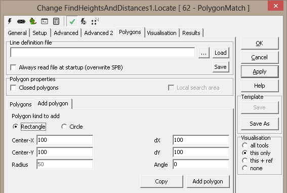
Point & Click Support
Two points will define a circle - first point is circle center and
the seconds defines the radius. Four points will define a rectangle.
Ctrl-Z will paste the clipboard to the tool. Ctrl-A will add the object
to the polygon vector list
Visualisation
|
Center |
Center of found polygon |
|
CenterAxes |
Orientation of match |
|
Description |
Description of accepted polygon (see Advanced2
page) |
|
Description (invalid) |
Description of non-accepted polygon (see
Advanced2 page) |
|
EdgePoints
|
|
|
EdgePointsOrig
|
|
|
FittedPoints
|
|
|
FittedPointsOrig
|
|
|
MatchedPolygon |
The best fitted polygon |
|
MissingPoints
|
|
|
MissingPointsOrig
|
|
|
NonAcceptedPolygon |
The original model is visualised when no match |
|
OriginalPolygon |
The original model |
|
OutlierPoints
|
|
|
OutlierPointsOrig
|
|
|
TraceLines |
Tracelines, final iteration |
|
TraceLinesOrig |
Tracelines, first iteration |
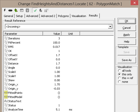
Results
|
Iterations
|
Number of performed iterations (less than
specified if no match)
|
|
Fit percent
|
Percent of tracelines that has a point that is
accepted
|
|
RMS |
RMS value of the fitted polygons |
|
OK |
1 if fit OK, 0 otherwise |
|
Offset X
|
Movement of fitted polygon, x |
|
Offset Y |
Movement of fitted polygon, y |
|
Distance |
Total movement of fitted polygon |
|
Angle |
Rotation of fitted polygon |
|
Scale X |
Scaling of fitted polygon, x |
|
Scale Y |
Scaling of fitted polygon, y |
|
Skew |
Axis skew |
|
Origin.x |
Position of base, x |
|
Origin.y |
Position of base, y |
|
Fitted points |
The final fitted edge points |
|
Fitted model |
The original model, moved to best position |
ExecuteCmd support (see also executeCmd)
|
Command
|
Parameters
|
Return values
|
Comments
|
| Set |
Object=ROI;Value=<polygon> |
ok,None |
Sets
the first ROI polygon. See Copy/paste
ROIs for details. (*) |
| Set |
Object=ROI;Number=<number>;
Value=<polygon> |
ok,None |
Sets
the numbered ROI polygon. See Copy/paste
ROIs for details. (*) |
| Add |
Object=ROI;Value=<polygon> |
ok,None |
Adds
ROI polygon to the end of the list. See Copy/paste
ROIs for details. |
| Get |
Object=ROI;Number=<number> |
ok,<polygon> |
Gets
numbered polygon, as Scorpion polygon (StrArr format). |
| Get |
Object=Tuple;Number=<number> |
ok,<tuple> |
Gets
numbered polygon, as Python tuple |
| Clear |
Object=ROI;Number=<number> |
ok,None |
Clears
numbered polygon (makes empty) |
| DeleteAll |
- |
ok,None |
Deletes
all polygons |
| SnapToModel |
- |
ok,None |
Replaces
active polygons with the best fit in the image. OK to run also when
the tool dialog is open. |
(*) Note: Polygon properties
are not supported by these methods, although existing properties will be
kept when the SET command is used.
Example 1: Copy a polygon from the clipboard
tool =  GetTool('PM')
tool.executeCmd('Set','Object=ROI;Number=1;source=clipboard')
Example 2: Copy a polygon to the clipboard
tool =  GetTool('PM')
tool.executeCmd('Get','Object=ROI;Number=1;destination=clipboard')
Example 3: Add model from Clipboard and Snap the model
pm=GetTool('StickerPosition')
pm.executeCmd('Set','Object=ROI;Number=1;source=clipboard')
ExecuteCmd('InspectExecute','')  # inspection needed for SnapToModel
pm.executeCmd ('SnapToModel','')
ExecuteCmd('InspectExecute','')
Keyboard shortcuts - More
information
|
Shortcut
|
Command
|
Comments
|
| Ctrl-Z |
Set
ROI |
Sets
the selected polygon to points marked in the image. If only a single
point is marked, the polygon is moved, centered around the point.
If the tool dialog is not open, the first polygon is set. |
| Ctrl-P |
Snap
to model |
Replaces
active polygons with the best fit in the image. OK to run also when
the tool dialog is open. |
| Ctrl-1
- Ctrl-0 |
Set
polygon 0-10 |
Sets
the numbered polygon to points marked in the image. If only a single
point is marked, the polygon is moved, centered around the point. If
a new polygon is defined this way, any missing polygons in between
are set as empty. |
| Ctrl-Shift-1
- Ctrl-Shift-0 |
Clear
polygon 0-10 |
Clears
the numbered polygon (sets empty). |
Example 4: Iterating Edge Mode when no match using Tool Scripting
# init
def init(self):
  tool = GetTool(self.name)
  tool.setConfigValue('EdgeSelect',0) # first
#afterExecute
def afterExecute(self):
  #use self.name to get this tool instance
  #Return 1 for OK, 0 for new execution
  tool = GetTool(self.name)
  ok = tool.getBoolValue('OK')
  edgeMode = tool.getConfigValue('EdgeSelect')
  if not ok and edgeMode < 2:
    tool.setConfigValue('EdgeSelect',3)
    print 'A_polygonfind retry edgeselect 3'
    return 0 # new execution
  else:
    return 1
|
