|
Tool Name:
|
Blob1 |
|
Tool
Index: |
61 |
|
Tool
Category: |
Basic Tools |
|
|
|
Description:
The Blob1 tool finds one or more (currently up
to 15) blobs, in the configured region of
interest (ROI).
A blob is a set of pixels
with similar properties, which are connected to
each other. The 'property' used for blob
detection by the Blob1 tool is the pixel
intensity value, as configured in the Blob1
tool. The boundary of a blob is called as
contour. Each blob may have 0 or more holes
inside it.
Blob area = A
Hole area 1 = H1
Hole area 2 = H2
Contour area = A+H1+H2
A more powerful
Blob4 tool is available in
the Advanced tools category.
Please refer to the
Locate detail with Blob
topic which demonstrates the configuration for
the blob detection.
User Interface:
(A) Tool Configuration dialog box -
Setup Tab
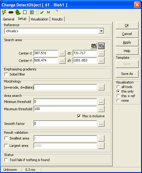
1. The æReferenceÆ drop down can be used to select the
input 2D reference. The input 2D reference provides the origin (0,0) and
rotation of the X and Y-axis. It is strongly recommended to click on the
'Apply' button available on the main tool
configuration window, to apply the newly
selected input reference. This reference is then
used while configuring all other tool
parameters.
2. The æSearch areaÆ group can be used for defining the
region of interest (ROI) for the æIntensityÆ tool processing. The æSearch
areaÆ is expected to be a rectangle.
3. æCenter-XÆ is used to provide the X co-ordinate of the
center of the search area rectangle. The co-ordinates are relative to the input
2D reference.
4. æCenter-YÆ is used to provide the Y co-ordinate of the
center of the search area rectangle.
5. æSize-XÆ is used to provide the size of the search area
in the direction of the X-axis as indicated by the input 2D reference.
6. æSize-YÆ is used to provide the size of the search area
in the direction of the Y-axis as indicated by the input 2D reference.
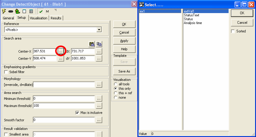
7. It is possible to type in fixed values for the æSearch areaÆ properties ¢
æCenter-XÆ, æCenter-Y, æSize-XÆ and æSize-YÆ. Also it is possible, to
specify dynamic values for each one of these properties, by assigning them
to any of the properties exposed from other tools defined in the Scorpion
profile. The æģÆ button available next to each of the æSearch areaÆ
properties user elements can be clicked to select a tool and its parameter
to be assigned.
8. The æCopyÆ button under the æSearch areaÆ can be used to
copy user defined region from the clipboard to the æSearch areaÆ properties.
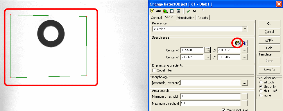
It is expected that a rectangle is defined on the image, by pressing the
CTRL keyboard key and simultaneously using mouse left button click to define
vertexes of the target rectangle. When æCopyÆ button is clicked, the search
area parameters are copied from the polygon on the image and are updated in
the æSearch areaÆ properties on the configuration dialog box. If use has not
defined a perfect rectangle, or has defined any other polygon, a bounding
rectangle is calculated and is used for updating the æSearch areaÆ
properties on the configuration dialog box.
If only single point is selected on the image, and æCopyÆ button is clicked,
only the center of the æSearch areaÆ is updated. Which means that the values
for æCenter-XÆ and æCenter-YÆ are updated whereas the values for æSize-XÆ
and æSize-YÆ are unchanged.
If only 2 or 3 points are selected on the image, and the æCopyÆ button is
clicked, it is ignored and has no effect.
9. The æPasteÆ button under the æSearch areaÆ can be used
to paste the æSearch areaÆ properties to the clipboard. This is useful in
viewing the exact location of the search area on the inspection image and
fine-tuning, if required.
10. The 'Sobel filter' check-box under the æEmphasizing
gradientsÆ group, can be enabled to
apply sobel filter on the input image before
processing for the blob detection.
11. The '[e=erode, d=dilate]'
textbox under the 'Morphology'
group can be used to apply erosion and dilation
operations on the located blob areas. The text
input expected in this text box is 'e<n>d<m>'
where <n> and <m> indicate numbers. E. g. e2d2e3
applies 2 pixels erosion, then 2 pixels dilation
and finally 3 pixels erosion. This is used
typically for smoothening of the blob
boundaries. It is possible to type in fixed
values for the æ[e=erode, d=dilate]Æ parameter,
it is also possible to specify dynamic value, by
assigning them to any of the properties exposed
from other tools defined in the Scorpion
profile. The æģÆ button available next to the
æ[e=erode, d=dilate]Æ can be clicked to select a
tool and its parameter to be assigned.
12. The æArea searchÆ group is used for specifying the blob
search parameters.
13. The 'Minimum threshold'
textbox is used to specify the minimum threshold
for the intensity value.
14. The 'Maximum threshold'
textbox is used to specify the maximum threshold
for the intensity value. If pixel intensity
value is greater than the minimum threshold and
is lesser than the maximum threshold, it is
considered as a blob pixel.
15. The 'Max is inclusive'
check-box can be checked to include the maximum
threshold in the detection range. If this is
checked, a pixel is considered as blob pixel, if
the pixel intensity value is greater than the
minimum threshold and is lesser than or equal to
the maximum threshold.
16. The 'Smooth factor' textbox
can be used to specify the blob contour
smoothening factor.
17. It is possible to type in fixed values for
the æArea searchÆ properties ¢ æMinimum
thresholdÆ, æMaximum threshold' and æSmooth
factorÆ. Also it is possible, to specify dynamic
values for each one of these properties, by
assigning them to any of the properties exposed
from other tools defined in the Scorpion
profile. The æģÆ button available next to each
of the æArea searchÆ properties user elements
can be clicked to select a tool and its
parameter to be assigned.
18. The 'Result validation'
group is used for configuring validation
settings for the detected blobs. The detected
blobs which do not follow these validations are
removed from the results. The result validation
settings are very useful for removing obvious
false detections and getting overall good
accuracy from the blob detection. The
Blob4 tool
has more advanced result validation, for further
pruning of the results for getting further
better accuracy.
19. The 'Smallest area'
check-box can be checked to enable the minimum
blob area validation. If blob area of any of the
detected blobs is lesser than the specified
smallest area threshold, it is removed from the
final list of detected blobs.
20. The 'Largest area'
check-box can be checked to enable the maximum
blob area validation. If blob area of any of the
detected blobs is greater than the specified
largest area threshold, it is removed from the
final list of detected blobs.
21. It is possible to type in fixed values for
the æResult validationÆ properties ¢ æSmallest
areaÆ and æLargest areaÆ. Also it is possible,
to specify dynamic values for each one of these
properties, by assigning them to any of the
properties exposed from other tools defined in
the Scorpion profile. The æģÆ button available
next to each of the æResult validationÆ
properties user elements can be clicked to
select a tool and its parameter to be assigned.
22. The 'Tool fails if nothing is found'
check-box under the 'Status'
group, can be checked to set the tool processing
result to 'fail', if no blob is detected in the
blob detection process. By default, the Blob1
tool processing result is set to 'pass',
whenever the tool processing is completed
successfully, irrespective of the number of
blobs detected.
Basic Processing
when the tool is executed:
1. If enabled, sobel filter is applied on the
input image. The result image is used for
further processing.
2. The intensity value for each of the pixels
from the specified region of interest (ROI) is
checked against the configured 'Area search'
thresholds.
3. If intensity value of the pixel is within the
configured 'Area search' threshold range, it is
marked as blob pixel.
4. Erosion and dilation operations are performed
on the detected blob pixels to enhance the
detection
5. Blob detection algorithm is executed to
identify blob pixels connected to each other, to
form blobs. There can be 0 or more blobs
available.
6. The detected blobs are validated against the
configured 'Result validation' parameters, to
remove the blobs which do not satisfy the blob
validation constraints.
|
Inputs to the
Tool: |
|
Inputs: |
1. Values of different tool parameters
used in the configuration, at the time of
processing, if dynamic values are used for
any of the configuration parameters |
|
Uses Reference: |
Yes, uses a
2D reference |
|
Uses Image: |
Yes |
|
|
|
|
Outputs
from the Tool: |
|
Outputs: |
| 1 |
Count: |
Numeric |
Number of valid blobs detected |
| 2 |
Coverage: |
Numeric |
Percentage of the total blob area of all blobs with respect to the total area of the specified region of interest (ROI) |
| 3 |
MaxArea: |
Numeric |
Largest value of contour area of a blob, from the detected blobs list. Contour area includes the area of holes, if they exist. |
| 4 |
MaxBlobArea: |
Numeric |
Largest value of blob area of a blob, from the detected blobs list. Blob area excludes the area of holes |
| 5 |
TotalArea: |
Numeric |
Total blob area of all blobs from the detected blobs list |
| 6 |
Intensity: |
Numeric |
Average intensity calculated across all pixels of the blob, from the detected blobs list; which has the largest contour area |
| 7 |
CenterOfGravity_x: |
Numeric |
X value of the center of gravity point of the blob, from the detected blobs list; which has the largest contour area |
| 8 |
CenterOfGravity_y: |
Numeric |
Y value of the center of gravity point of the blob, from the detected blobs list; which has the largest contour area |
| 9 |
ContourArea[<n>]: |
Numeric |
Contour area of 'n' th blob in the list of detected blobs |
| 10 |
ContourLength[<n>]: |
Numeric |
Contour length of 'n' th blob in the list of detected blobs |
| 11 |
BlobArea[<n>]: |
Numeric |
Blob area of 'n' th blob in the list of detected blobs |
| 12 |
HoleCount[<n>]: |
Numeric |
Number of holes in 'n' th blob in the list of detected blobs |
| 13 |
Intensity[<n>]: |
Numeric |
Average intensity calculated across all pixels of 'n' th blob in the list of detected blobs |
| 14 |
CenterOfGravity[<n>]_x: |
Numeric |
X value of the center of gravity point of 'n' th blob in the list of detected blobs |
| 15 |
CenterOfGravity[<n>]_y: |
Numeric |
Y value of the center of gravity point of 'n' th blob in the list of detected blobs |
| 16 |
StatusText: |
Text |
This is a standard output from all Scorpion tools and describes the processing status |
| 17 |
Status: |
Numeric |
This is a standard output from all Scorpion tools and indicates error/success of the tool processing. 1 indicates success and 0 indicates error |
| 18 |
AnalyzeTime: |
Numeric |
This is a standard output from all Scorpion tools and indicates the time taken by the last processing operation of this tool
|
|
|
Visualizations: |
| 1 |
AllBlobs: |
Displays the boundary lines of all detected blobs |
| 2 |
AllCenters: |
Displays center of gravity points for all detected blobs |
| 3 |
AllHoles: |
Displays the boundary lines of all detected holes inside all detected blobs |
| 4 |
CenterOfGravity: |
Displays the center of gravity point of the detected blob with largest contour area |
| 5 |
Error: |
Displays error indicator cross mark, at the center of the ROI, if no blobs are detected |
| 6 |
MaxContour: |
Displays the boundary line of the detected blob with largest contour area |
| 7 |
ROI: |
Displays the region of interest rectangle
|
|
|
Reference
outputs: |
| 1 |
2D Reference: |
Input 2D reference, translated to the center of gravity point of the detected blob, which has the largest contour area |
|
|
|
|
|
Templates: |
|
Supports
Templates: |
Yes |
|
|
|
|
ExecuteCmd Support:
More
information |
| |
Command |
Arguments |
Return value |
Description |
| 1 |
ōSetö |
ōObject=ROI;Value=<polygon>ö
where <polygon> is the array of polygon
vertex points indicating region of interest
(ROI) |
Tuple,
where
first element indicates success(1) or
failure (0) |
Sets the search area |
| 2 |
"Set" |
ōObject=ROI;Value=<cx>,<cy>,<dx>,<dy>ö
where <cx> is the X co-ordinate of the
center of the rectangle,
<cy> is the Y co-ordinate of the center of
the rectangle,
<dx> is the size of the rectangle in X
direction,
<dy> is the size of the rectangle in Y
direction |
Tuple,
where
first element indicates success(1) or
failure (0) |
Sets the search area |
| 3 |
"Get" |
ōObject=ROIö |
Tuple,
where
first element indicates success(1) or
failure (0),
second element is an array indicating the
search area rectangle polygon |
Gets the search area |
Please refer to the Copy/paste
ROIs for more information on 'Copy Paste ROI using
executeCommand'.
|
