|
Setup
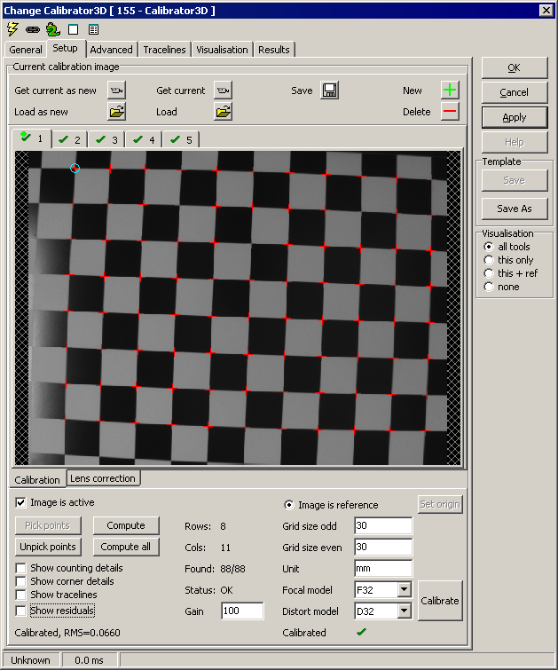
These controls let you manipulate the
calibrator images:
- Get current as
new - extract the current
Scorpion image to a new tab
-
Get current - extract the current Scorpion image, replacing any
showing
-
Save - save current image to file
-
Load as new - load an image from file to a new tab
-
Load - load an image from file, replacing any showing
-
New - add new, empty tab
-
Delete - delete current tab
Each tab has an icon attached - these
icons convey the status of the image:
 - Image is active and enough
corners have been located - Image is active and enough
corners have been located - Image is active and enough
corners have been located. Image is the reference pose image - Image is active and enough
corners have been located. Image is the reference pose image - Image is active, but
has failed location of enough
corners - Image is active, but
has failed location of enough
corners -
Image is inactive -
Image is inactive
These controls let you tune the
calibration process:
- Image is active - when
unchecked, the currently shown image is not part of the calibration
process.
- Image is reference - one of
the images must define the reference pose of the object
- Set origin - for the
reference image, you can Ctrl-click in the vicinity of a corner and
press this button. This will set the object reference system origin.
- Pick points - when exactly
four points are Ctrl-clicked in the image, use this button to define the
rectangle surrounding the squares to be used for calibration. This
action also initiates a Compute.
- Unpick points - reverse the
pick points process, returning the four corners as editable
markers in the image
- Compute - apply a set of
linefinders to count the number of squares within the picked rectangle,
and then locate as many corners as possible
- Compute all - repeat the
compute process for all active images
- Show counting details -
display edge points and lines resulting from the square counting process
- Show corner details -
display edge points and lines resulting from the corner detection
process
- Show tracelines - also show
tracelines from either of the above two options
These controls describe the object and
algorithm:
- Grid size odd - size of
squares 1, 3, 5 etc. in the grid *
- Grid size even - size of
squares 2, 4 etc. in the grid *
- Unit - object size unit.
Usually mm or in
- Focal model - the camera
model (intrinsic parameters):
- F32
- Full focal model: rectangular pixels, skew
- F22
- Rectangular pixel model, no skew
- F12
- Square pixel model, no skew
- Distort model - the lens
distortion model:
- D32
- 3 radial and 2 tangential distortion parameters
- D22
- 2 radial and 2 tangential distortion parameters
- D30
- 3 radial distortion parameters
- D20
- 2 radial distortion parameters
- D1
- Fast distortion model, single radial parameter
These controls are for information only:
- Show residuals - after
calibration, each corner has a residual error. This is displayed as an
arrow
- Gain - size (gain) of these
arrows (Press Calibrate to redisplay.)
- Rows - number of grid rows
found
- Cols - number of grid
columns found
- Found xx/xx - number of
corners found/number of corners present in grid
- Status - OK or Fail. Each
image has its own status
These controls are for the calibration
itself:
- Calibrate - do the full
calibration based on the images and settings
- Calibrated/Not calibrated -
the current status for the calibrator
When calibration is successful, the word
Calibrated and a green tickmark appears below all controls.
A number of
messages will appear to the left of the Calibrated/Not calibrated message.
These messages indicate e.g. calibration success/failure, and other messages
appear when needed.
Lens correction
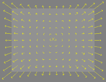
This tab displays an informational view
of the distortion corrections. the set of arrows displays the inverse
distortion, i.e. the correction applied at each point to remove the lens
distortion. The gain field sets the length of the displayed arrows. (Press
Calibrate to recalculate.)


Advanced

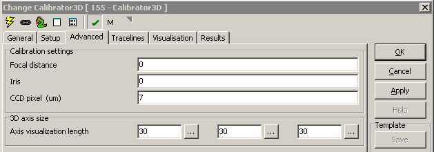
These are purely informational parameters that are stored with the calibrator
model.
- Focal distance - camera setting
- Iris - camera setting
- CCD pixel (um) - CCD pixel (vertical) size. This is also used to
calculate the lens' focal length
3D axis size
- Axis visualization length - size of the displayed arrows for
the reference system.
Tracelines
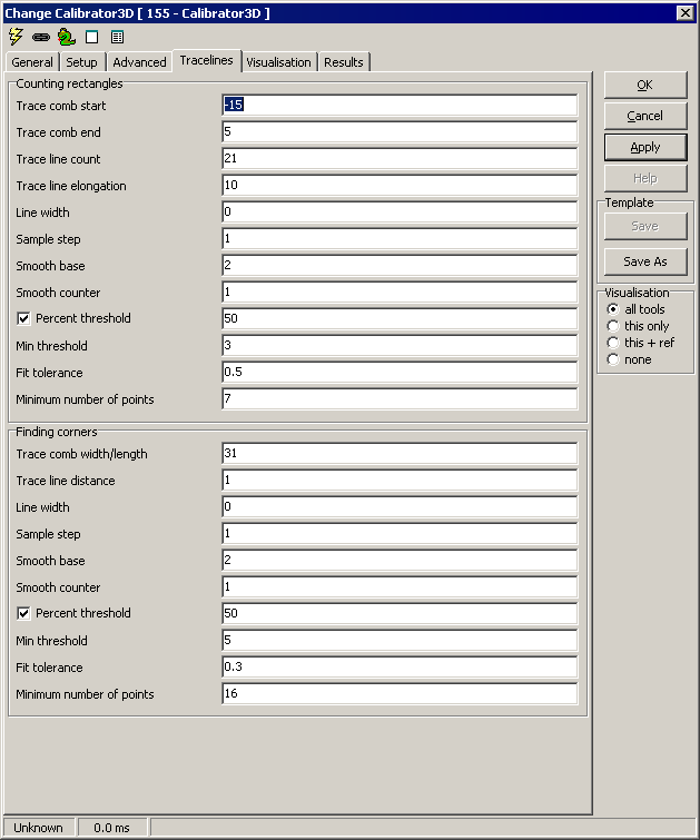
These settings are used for the linefinders that count the squares in the
image, and those that find the corners within the image, respectively:
Counting rectangles
This works by creating tracelines between your four marked corner points.
The lines thus found are used to count the number of transitions between the
corners, and to more accurately position the corners themselves.
- Trace comb start/end - width of the trace comb, in pixels, on
the outside/inside of the corner points
- Trace line count - number of trace lines
- Trace line elongation - extra length of the tracelines
outside each corner point
- Line width - width in pixels of each trace line
- Sample step - interval in pixels between each sample
- Smooth base - smooth filter length
- Smooth counter - smooth filter count
- Percent threshold - if checked, calculate threshold
dynamically
- Min threshold - minimum dynamic threshold, or manual
threshold
- Fit tolerance - max distance from edgepoint, in pixels, for
line fit
- Minimum number of points - minimum count to define a line
Finding cormers
This is done by applying a linear model (perspective) based on the four
corners found above, and looking for edges near where the linear model
postulates they should be.
- Trace comb width/length - width and length of each trace
comb, respectively
- Trace line distance - distance in pixels between each
traceline
- Line width - width in pixels of each trace line
- Sample step - interval in pixels between each sample
- Smooth base - smooth filter length
- Smooth counter - smooth filter count
- Percent threshold - if checked, calculate threshold
dynamically
- Min threshold - minimum dynamic threshold, or manual
threshold
- Fit tolerance - max distance from edgepoint, in pixels, for
line fit
- Minimum number of points - minimum count to define a line

Visualisation
|
ChildAxes
|
The established 3D coordinate system
(2D and/or 3D) |
|