Note that the tool must be connected to the image index of the first
reference.
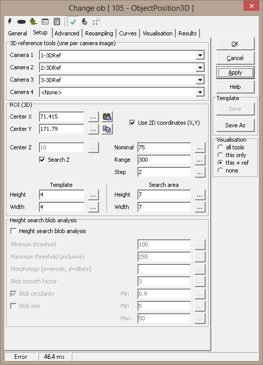
ROI (3D)
- Center
X
- Center Y
- Use 2D Coordinates -
- X and Y can be
specified using 2D coordinates.
- The Z coordinate will
necessarily still need to be a 3D coordinate
- Center Z - defines the 3D center point in 3D coordinates
- Search Z - autodetect the Z value by scanning different values:
- Nominal - middle Z scan value
- Range - spread around the nominal value
- Step - increment
- Template Height, Width - defines the size of the used template
in 3D coordinates
- Search area Height, Width - defines the size of the correlation region
used to match
the template with the other images in 3D coordinates. Must be
larger than Template Height, Width.
Include in on-screen-description - requires description to be
active under Visualisation
- Match - (for Correlation search only - see Advanced)
- match between images
- 3D Coordinates - the position found
- Deviation - deviation found (see Advanced)
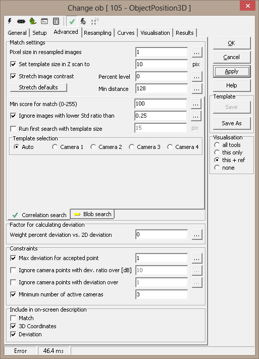
Advanced
Match settings
- Pixel size in resampled images - the approximate ratio of
original to resampled pixels used in template match. Always used in the
final search, but can be overridden for initial loops (this to reduce
processing time). Override is given in the next option
- Set template size in Z scan to (pixels) - use this size
for the template in initial scan to estimate the Z value
- Stretch image contrast - optimise image contrast.
This is most effective for blob search, and has less
effect for correlation search
- Percent level - contrast stretch setting
- Min distance - contrast stretch setting
- Stretch defaults - set Percent level and
Min distance to default values
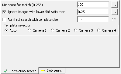
Correlation search
Resampled images are correlated, and maximum correlation
factor determines the match position.
-
Min score for match (0-255)
- cross correlation match threshold
-
Ignore images with lower Std
ratio than - ignore featureless images
- Run first search with template size (pixels) - run two loops
to locate points, first a coarse search for approximate location, then a
refined search for accurate placement. This can give a significate speed
improvement.
-
Template selection
-
Auto - use best image as template in cross-correlation
algorithm
-
Camera 1-4 - use fixed image as template
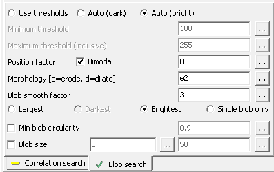
Blob search
Blobs are searched within the resampled images, and the
center of gravity of a blob is used to determine the match
position.
- Use thresholds - manually set thresholds
- Auto (dark) - see description below
- Auto (bright) - see description below
- Minimum threshold - for manually set thresholds
- Maximum threshold (inclusive) - for manually set
thresholds
- Position factor - see description below
- Bimodal - see description below
- Morphology (e=erode, d=dilate) - erode or dilate
blobs
- Blob smooth factor - blob smoothing
- Largest/Darkest/Brightest/Single blob only - only
a single blob will be used for positioning; you can here
select which. If you choose Single blob only, the
search will fail if more blobs are within the search area.
Auto thresholding
A threshold is set based on the resampled image's histogram.
- If Bimodal is checked, the histogram should have
two distinct tops (i.e., two major gray levels). A threshold
is calculated assuring maximum separation.
- If Bimodal is not checked, the histogram is
assumed not bimodal. A threshold is still found to separate
the image, but since tops in the histogram are not assumed,
the centre of gravity of the histogram on each side of the
threshold is used as a "top" instead.
- The Position factor determines the reported
threshold. 0 means the optimum threshold, -1 means the
darker top, +1 means the brighter top. Anything in between
leads to linear interpolation between a top and the
threshold.
Factor for calculating deviation
There are two
deviation measures calculated for each point:
- The first (aka. Deviation or 3D
Deviation) measures how well the observed points
coincide in 3D space.
A 3D point is found as the intersection
of two or more 3D lines, one line from each camera. The lines are the
"inverse projections" of the 2D points into space. When two
lines do not meet exactly in space, the deviation is half of the
shortest distance between them. i.e., by how much the point result
deviates from the lines. When more that two cameras are used, the
deviations are averaged.
Deviation is given in physical coordinates and reflects 3D camera
calibration
- The second (2D deviation) is
calculated by mapping the found 3D point back to the
camera image, and measuring the distance from this point
to the incoming 2D point. A large error here could mean
that the tools producing the 2D points have missed.
The weight percent lets you use either deviation measure
or both:
- Weight percent deviation vs. 2D deviation
- 100% means use 3D deviation only; 0%
means 2D deviation only. Or you can select a
combination. Generally this is sound, since the 2D and
3D measurements are in the same dimension (usually mm).
Constraints
-
Max deviation for accepted
point - acceptance criterion for each point (see Deviation
above)
- Ignore camera points with deviation ratio over
[dB] - ignore cameras where 3D deviation
ratio to the best camera is over the threshold - measured in dB
-
Ignore camera points with deviation over - used to remove
"bad" points before estimating position in space
-
Minimum number of active cameras - only succeed if at least this
number of cameras is accepted. This is especially useful in combination
with the Template selection (above)
Resampling
The best match in the Z scan is displayed to the left.
For Correlation search, the used template and the search areas from the other cameras are
displayed to the right. The template will be the smaller image.
For Blob search, the same size is used for all resampled images.
All blobs found in the images are drawn in red, and if only one blob is
found, or if you select the largest/darkest/brightest as the result, it will
be drawn in green. The center of gravity for this blob is the position used
to locate a 3D point.
You will also see the effect ov Contrast stretching in these
images. Below the left image is original, the right image has been contrast
stretched.
Original:  Contrast stretched:

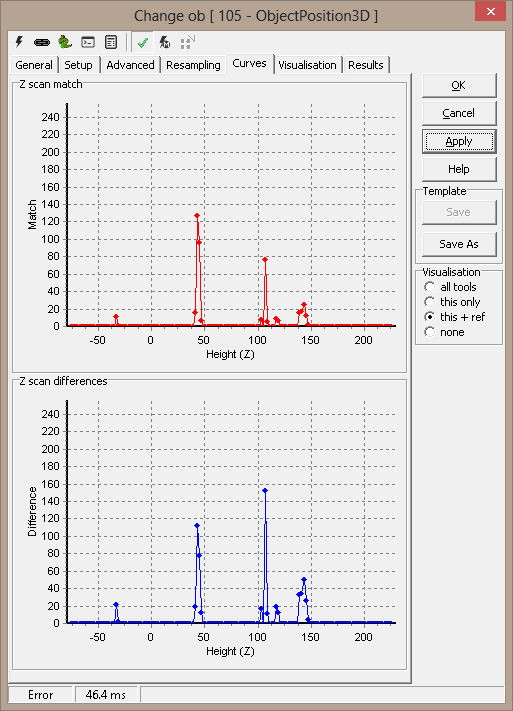
Curves
A set of curves is supplied for z scan analysis. For each step in the Z
scan loop, the image correlation factors are averaged and plotted (Match).
Another plot (Differences) show how the correlation factors for the
different comparisons differ.
Visualization
|
AcceptedPoint |
The found 3D point |
|
Blob |
For blob search, the used blob |
|
FailDescription |
Description for point with too high deviation |
|
FailedPoint |
3D point with too high deviation |
|
OKDescription |
Description for accepted point |
|
ROI |
The area used to extract the template |
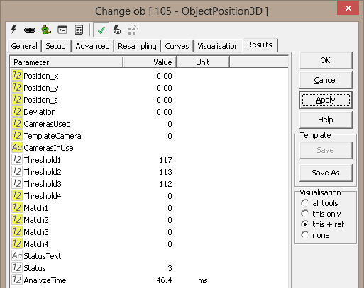
Results
|
Position.x |
X position for found 3D point |
|
Position.y |
Y position for found 3D point |
|
Position.z |
Z position for found 3D point |
|
Deviation |
Point deviation |
|
Cameras used |
Number of cameras not ignored due to constraints |
|
Template camera |
The camera selected to use as the template (will have a Match of 0).
(Correlation search only) |
|
Cameras in use |
Python tuple of the cameras used to generate the result |
|
Threshold1 |
Blob threshold for camera 1 (Blob search only) |
|
Threshold2 |
Blob threshold for camera 1 (Blob search only) |
|
Threshold3 |
Blob threshold for camera 1 (Blob search only) |
|
Threshold4 |
Blob threshold for camera 1 (Blob search only) |
|
Match1 |
Template match for camera 1 (0-255) (Correlation search only) |
|
Match2 |
Template match for camera 2 (0-255) (Correlation search only) |
|
Match3 |
Template match for camera 3 (0-255) (Correlation search only) |
|
Match4 |
Template match for camera 4 (0-255) (Correlation search only) |
| Tool
Features: |
| Supports Templates: |
Yes |
| Support Threading |
Yes |
| Result reference |
Yes |