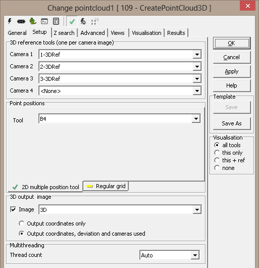
Setup3D reference tools (one per camera image)
- Camera 1-4 - a 3D reference is needed per camera
Point positions
You can use an external tool or a regular grid to set up the positions
for creating the cloud:
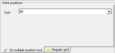
2D multiple position tool
- Tool - A tool with multiple point results. Currently, these
tool types are supported: Blob2, Blob3, Blob4, TemplateFinder2,
TemplateFinder3
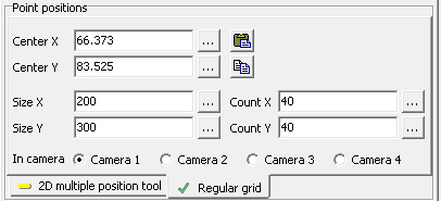
Regular grid
- Center X/Y - ROI center
- Size X/Y - ROI size
- Count X/Y - Number of dots within ROI in X and Y
directions
- In camera - Use 2D coordinate system from the selected
camera
Z
search
-
Nominal/Range/step -
search parameters for initial height search
-
Template height/width
- size of template (in reference coordinates)
-
Search height/width
- size of rectangle for cross correlation search
- Prohibit reuse of image points - a position that has
already been identified as a match will not be a candidate for later
matches. Helps reduce false detections
- Min accepted correlation - early exit for mismatches
- Min acepted Std ratio - ignore featureless images
3D output image
- Image - image to store and display the generated point cloud.
May be deselected for string output only (below)
- Output coordinates only - only the X,Y,Z coordinates are
stored
- Output coordinates, deviation and cameras used - 5-element
points are stored (not currently useful)
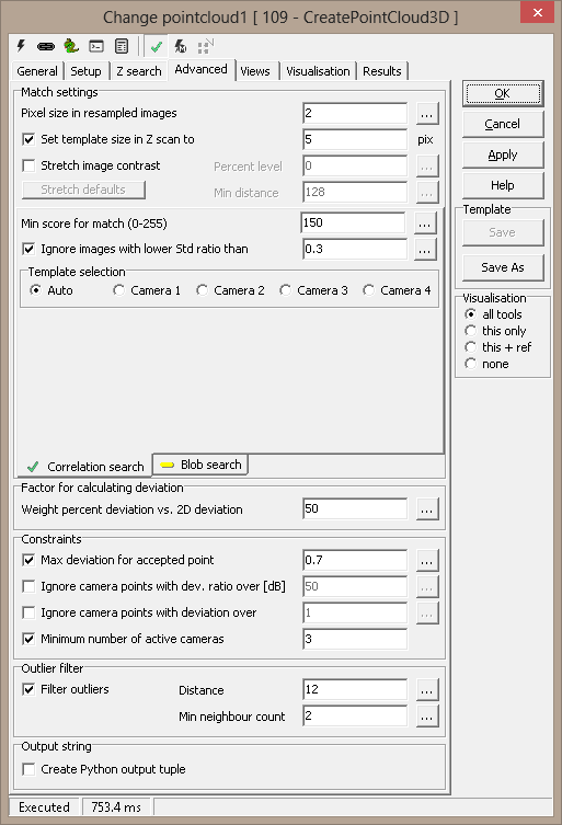
Advanced
Match settings
-
Pixel size in resampled images
- change to speed up processing
-
Set template size in Z scan
to - change to speed up initial height search
- Stretch image contrast - optimise image contrast.
This is most effective for blob search, and has less
effect for correlation search
- Percent level - contrast stretch setting
- Min distance - contrast stretch setting
- Stretch defaults - set Percent level and
Min distance to default values
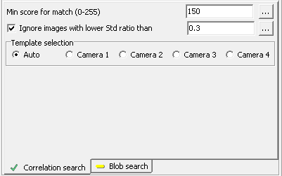
Correlation search
Resampled images are correlated, and maximum correlation
factor determines the match position.
-
Min score for match (0-255)
- cross correlation match threshold
-
Ignore images with lower Std
ratio than - ignore featureless images
-
Template selection
-
Auto - use best image as template in cross-correlation
algorithm
-
Camera 1-4 - use fixed image as template
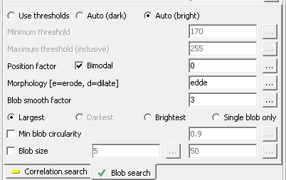
Blob search
Blobs are searched within the resampled images, and the
center of gravity of a blob is used to determine the match
position.
- Use thresholds - manually set thresholds
- Auto (dark) - see description below
- Auto (bright) - see description below
- Minimum threshold - for manually set thresholds
- Maximum threshold (inclusive) - for manually set
thresholds
- Position factor - see description below
- Bimodal - see description below
- Morphology (e=erode, d=dilate) - erode or dilate
blobs
- Blob smooth factor - blob smoothing
- Largest/Darkest/Brightest/Single blob only - only
a single blob will be used for positioning; you can here
select which. If you choose Single blob only, the
search will fail if more blobs are within the search area.
Auto thresholding
A threshold is set based on the resampled image's histogram.
- If Bimodal is checked, the histogram should have
two distinct tops (i.e., two major gray levels). A threshold
is calculated assuring maximum separation.
- If Bimodal is not checked, the histogram is
assumed not bimodal. A threshold is still found to separate
the image, but since tops in the histogram are not assumed,
the centre of gravity of the histogram on each side of the
threshold is used as a "top" instead.
- The Position factor determines the reported
threshold. 0 means the optimum threshold, -1 means the
darker top, +1 means the brighter top. Anything in between
leads to linear interpolation between a top and the
threshold.
Factor for calculating deviation There are two
deviation measures calculated for each point:
- The first (aka. Deviation or 3D
Deviation) measures how well the observed points
coincide in 3D space.
A 3D point is found as the intersection
of two or more 3D lines, one line from each camera. The lines are the
"inverse projections" of the 2D points into space. When two
lines do not meet exactly in space, the deviation is half of the
shortest distance between them. i.e., by how much the point result
deviates from the lines. When more that two cameras are used, the
deviations are averaged.
Deviation is given in physical coordinates and reflects 3D camera
calibration
- The second (2D deviation) is
calculated by mapping the found 3D point back to the
camera image, and measuring the distance from this point
to the incoming 2D point. A large error here could mean
that the tools producing the 2D points have missed.
The weight percent lets you use either deviation measure
or both:
- Weight percent deviation vs. 2D deviation
- 100% means use 3D deviation only; 0%
means 2D deviation only. Or you can select a
combination. Generally this is sound, since the 2D and
3D measurements are in the same dimension (usually mm).
Constraints
-
Max deviation for accepted
point -
acceptance criterion for each point
(see Deviation above)
-
Ignore camera points with
dev. ratio over [dB] - Ignore camera points with deviation ratio over
[dB] - ignore cameras where 3D deviation
ratio to the best camera is over the threshold - measured in dB
-
Ignore camera points with
deviation over - used to remove "bad" points
before estimating position in space
-
Minimum number of active
cameras - only succeed if at least this
number of cameras is accepted. This is especially useful in
combination with the Template selection (above)
Outlier filter
- Filter outliers - remove points without
neighbours
- Distance - distance to neighbours
- Min neighbour count - minimum count of neighbours
within distance to keep point
Output string
- Create Python output tuple - Python tuple of tuples with 5
elements per sample: X, Y, Z, deviation, cameras used. Useful for
scripting
Runtime viewsTo
investigate tool performance, you can select a single point index and
display resampled images and Z search match plots.
Select point
- Point index - index of one
of the input (or grid) points. Index starts at 1
- Point position (X,Y) - the
point position (in object coordinates) is displayed. This helps locating
the point in the main image
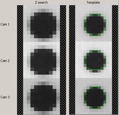
Resampling
The best match in the Z scan is displayed to the left.
For Correlation search, the used template and the search areas from the other cameras are
displayed to the right. The template will be the smaller image.
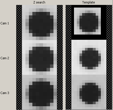
For Blob search, the same size is used for all resampled images.
All blobs found in the images are drawn in red, and if only one blob is
found, or if you select the largest/darkest/brightest as the result, it will
be drawn in green. The center of gravity for this blob is the position used
to locate a 3D point.
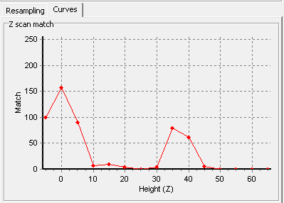
Curves
A match curve is supplied for z scan analysis. For each step in the Z
scan loop, the image correlation factors are averaged and plotted (Match).
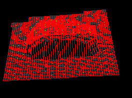
Visualisation
|
AcceptedPoint |
points passing constraints |
|
Blob |
for blob search, the used blobs |
|
FailedPoint |
points rejected by constraints |
|
PointIn |
all points from 2D tool |
Axis - individual color for all axis
Results
|
Points in |
number of points from 2D tool |
|
Points found |
number of accepted points |
|
Outliers removed |
number of outliers removed |
|
Percent accepted |
percentage of points passing |
|
Min deviation |
best fit |
|
Max deviation |
worst fit |
|
Mean deviation |
mean fit |
|
Std deviation |
standard deviation for fit |
|
Results |
optional Python string with all results |
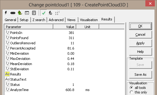
|