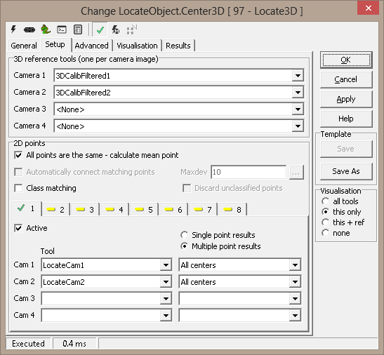
2D points - up to 8 points to locate
These are 2D tool results, where an object is located in two or more
cameras. For each camera, you must use the same reference system for these
tools as you use for the 3D reference tool. (Or, more precisely, these
tools' Result reference system must be the same as the 3D reference
tool's.)
- All points the same - calculate mean point - a mode in which
all observed points will actually be the same, measured with different
tools. The mean 3D point and a spread is reported; this will
reduce the noise level in the result, and gives an additional quality
measure.
- Automatically connect matching points - run a matching
algorithm to pair corresponding points. If not set, the Tool/Result
sets from each camera must match exactly.
- Z range - limit Z range when searching for matching points
(smart to use if you have a rough idea of the Z value - reduces the
chance for false matches)
1 - 8
-
Active - toggle
calculation of this point
- Tool - tool that reports
a point
- Result - which point
result to use
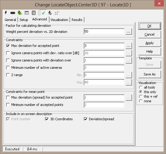
Advanced
Factor for calculating deviation
There are two deviation measures calculated for each point:
- The first (aka. Deviation or 3D Deviation)
measures how well the observed points coincide in 3D space.
A 3D point is found as the intersection
of two or more 3D lines, one line from each camera. The lines are the
"inverse projections" of the 2D points into space. When two
lines do not meet exactly in space, the deviation is half of the
shortest distance between them. i.e., by how much the point result
deviates from the lines. When more that two cameras are used, the
deviations are averaged.
Deviation is given in physical coordinates and reflects 3D camera
calibration
- The second (2D deviation) is calculated by mapping the
found 3D point back to the camera image, and measuring the distance from
this point to the incoming 2D point. A large error here could mean that
the tools producing the 2D points have missed.
The weight percent lets you use either deviation measure or both:
- Weight percent deviation vs. 2D deviation
- 100% means use 3D deviation only; 0% means 2D
deviation only. Or you can select a combination. Generally this is
sound, since the 2D and 3D measurements are in the same dimension
(usually mm).
Constraints
-
Max deviation for accepted
point - acceptance
criterion for each point (see Deviation above).
- Ignore camera points with deviation ratio over
[dB] - ignore cameras where 3D deviation
ratio to the best camera is over the threshold - measured in dB
-
Ignore camera points with deviation over - used to remove
"bad" points before estimating position in space
-
Minimum number of active cameras - accept point only if at least
this many cameras have a valid result
Constraints for mean point
This is active only if All points the same is checked on the Setup
page. All found points are averaged and results taken from there.
-
Max deviation (spread) for accepted
point - acceptance
criterion for the common (mean) point. The spread is calculated
in 2D as the maximum distance from the incoming tool points to the mean
point.
-
Minimum number of accepted points - accept mean point only if at least
this many points have a valid result.
Include in on-screen-description - requires description to be
active under Visualisation
- Point number - (not available if All points the same
is checked)
- 3D Coordinates
- Deviation/spread
Visualisation
|
AcceptedPoint |
Point that passes constraints |
|
FailDescription |
Description of a failed point |
|
FailedPoint |
Found point that fails constraints |
|
IncomingPoint |
Input points from other tools |
|
OKDescription |
Description of an accepted point |
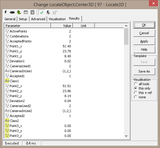
Results
|
Point[1-8].x |
X position for found 3D point |
|
Point[1-8].y |
Y position for found 3D point |
|
Point[1-8].z |
Z position for found 3D point |
|
Deviation[1-8] |
Point deviation |
|
Cameras used[1-8] |
Number of used cameras for point |
|
Cameras in use[1-8] |
Python tuple of the cameras used to generate the result |
|
Accepted[1-8] |
Constraints result (0=fail, 1=accepted) |
|
Mean point (.x,.y,.z) |
Mean of found points (only for all points are the same) |
|
Spread |
Max distance from single point to the mean |
|
Active points |
Count of active input points |
|
Accepted points |
Count of points accepted and reported |
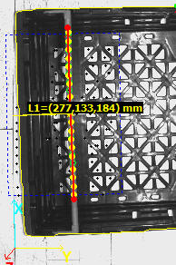
Example 1: Measure Distance Between Points
import math

def Distance3D (x1,y1,z1,x2,y2,z2):
   return math.sqrt((x1-x2)*(x1-x2) + (y1-y2)*(y1-y2) + (z1-z2)*(z1-z2))

def GetPoint3D(name):
  x = GetFloatValue(name+'_x')
  y = GetFloatValue(name+'_y')
  z = GetFloatValue(name+'_z')
  return x,y,z

def SetPoint3D(name,x,y,z):
  SetFloatValue(name+'_x',x)
  SetFloatValue(name+'_y',y)
  SetFloatValue(name+'_z',z)

x1,y1,z1 = GetPoint3D('Points3D1.Point1')
x2,y2,z2 = GetPoint3D('Points3D1.Point2')
x3,y3,z3 = GetPoint3D('Points3D1.Point3')

width = Distance3D(x1,y1,z1,x2,y2,z2)
height = Distance3D(x1,y1,z1,x3,y3,z3)

print 'w,h -',width,height